SAF OPAL Pro MS6 User Manual
Page 29
MS6 REDUCED VOLTAGE STARTER
Page 28
9 SPARES
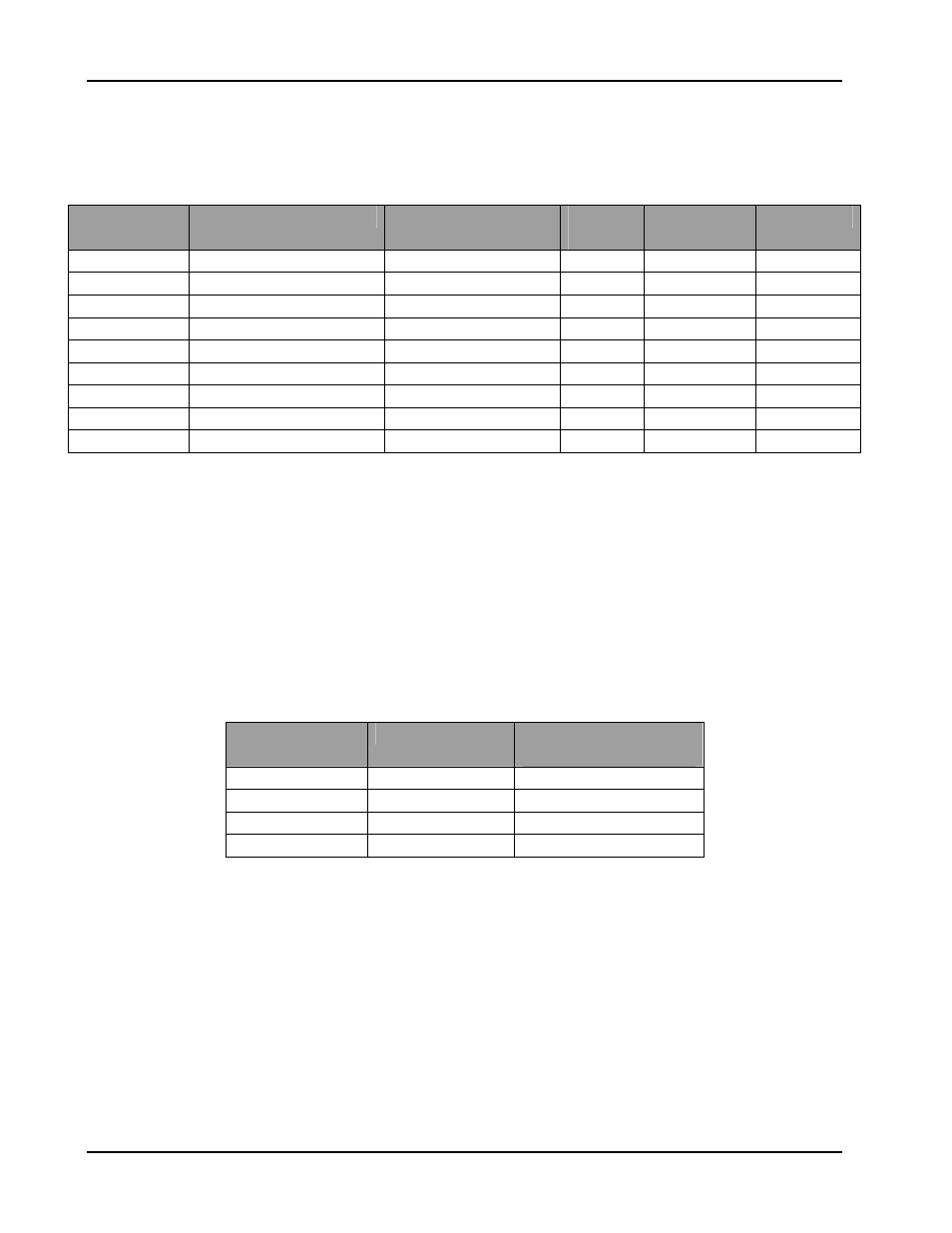
9.1 SPARE PARTS
Model
SCR
Current
Transformer
Control
Card
Stack ID
Card
MOV
MS6-30
N10SP03(61A SCR)
T261123 (1500:1)
CA530
CA532(30)
O210050
MS6-50
N10SP06(90A SCR)
T261123 (1500:1)
CA530
CA532(50)
O210050
MS6-80
N10SP16(140A SCR)
T262320 (2500:1)
CA530
CA532(80)
O210050
MS6-125
N728352(300A SCR)
T262320 (2500:1)
CA530
CA532(125) O210050
MS6-250
N728452(580A SCR)
T262320 (2500:1)
CA530
CA532(250) O210050
MS6-420
N718602(720A SCR)
T265320 (5000:1)
CA530
CA532(420) O210050
MS6-500
N718133(1100A SCR)
T268320 (8500:1)
CA530
CA532(500) O210050
MS6-600
N718153(1200A SCR)
T268320 (8500:1)
CA530
CA532(600) O210050
MS6-800
N718552(1500A SCR)
T261321 (10000:1)
CA530
CA532(800) O210050
9.2 SCR INSTALLATION PROCEDURE
• Clean both heat sink and SCR surfaces.
• Apply a thin layer of joint compound (Noalox) to both SCR surfaces.
• Observe correct SCR polarity.
• Install SCR so that roll pins engage dimples on both sides of the SCR.
• Tighten clamp bolts evenly until finger-tight.
• Tighten each bolt according to table below (based on number of spring bars and size of
bars).
Note: SMALL clamps are 10.5cm(4.25inches) and LARGE clamps are 12.5cm(5inches)
CLAMP SIZE
SPRING BARS BOLT TURNS PAST
FINGER TIGHT
SMALL 1
0.75
SMALL 2
1
LARGE 3
1.75
LARGE 4
1.75