Specifications – Rose Electronics Remote Control Switch User Manual
Page 5
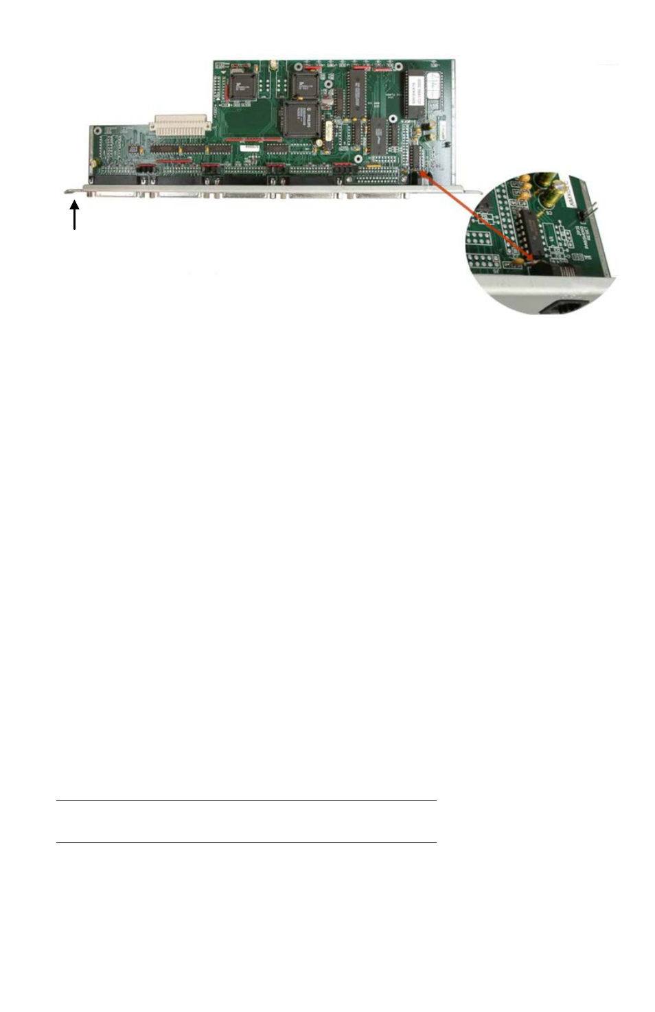
Figure 1. Replacing Resistor R4
Specifications
Part numbers
RCS-2RS/xx
2-Port model
RCS-4RS/xx
4-Port model
Options: (/xx)
/RJ - RJ11F Serial Interface
/SW – External power adapter
• Serial Interface Options:
/RJ - RJ11F Serial Interface
/D9 - DB9M Serial Interface
• Panel Mount Option
/PMSR Panel Mount
/GCRA Color sequence - Green,
Clear, Red, Amber
Externally Powered
/SW
Optional Power Supply
Part # TFR-05D200FSUP-3.5
Cables: CAB-06RJnnn RJ11 6-conductor Data Cable
Dimensions Width Depth Height
Weight
5.0”
2.0”
1.0”
0.25 lbs
12.7
5.1
2.54 cm
0.11 kg
Connectors
Serial RJ11F / DB9
External power: 3.5mm on /SW Power Option
Indicators
LED Port selection (in button)
Chassis
Electro-galvanized steel, Black powder coated
Environmental 0° - 45°C / 32°F - 113°F, 5%-80% non-condensing RH
1- Remove securing screws from each end of the CPU
card the RCS will be connected to
2- Carefully remove the card from the chassis backplane,
pull the card straight back
3- Locate 1K resistor R4 (directly behind the RJ45
connector) and replace the 1K resistor with a 10 Ohm,
1/4 watt, 5% resistor
4- Reinstall the CPU card in the chassis and apply power
Resistor R4