Operation – Rose Electronics CrystalView DVI Quad User Manual
Page 30
OPERATION
CRYSTALVIEW DVI QUAD INSTALLATION AND OPERATIONS MANUAL
26
Operation
USB HID (keyboard and mouse)
Extenders with USB HID connectors support ONLY keyboard and mouse. It is possible that other Human
Interface Devices (e.g. touchscreens, graphics tablets, barcode readers) will work correctly, but it is not
guaranteed. Non-HID devices such as scanners, printers, cameras and flash memory sticks will not work with
the USB HID ports of the CrystalView DVI Quad Extender. The Extender supports two USB HID devices at a
time, such as keyboard and mouse or keyboard and touchscreen, but not keyboard and mouse and
touchscreen at the same time. A USB Hub can used, but it will not increase the number of HID devices
simultaneously supported to more than two.
The DDC, Next frame switching, and color selection on the CrystalView DVI Quad are factory set to values that
satisfy most applications. These default settings can be modified, if needed, to the following:
Default settings
DDC Information – Use the internal DDC table.
Color selection – Automatically switch between 16 Bit and 24 Bit
Next frame switching – Switch to a new frame during Hsync period
DDC manual settings
The DDC information supplied to the CPU can be set to:
1.
The Transmitter unit’s internal DDC table (default)
2.
The DDC information obtained from a monitor locally connected to the transmitter unit
3.
The DDC information obtained from a monitor connected to the receiver unit
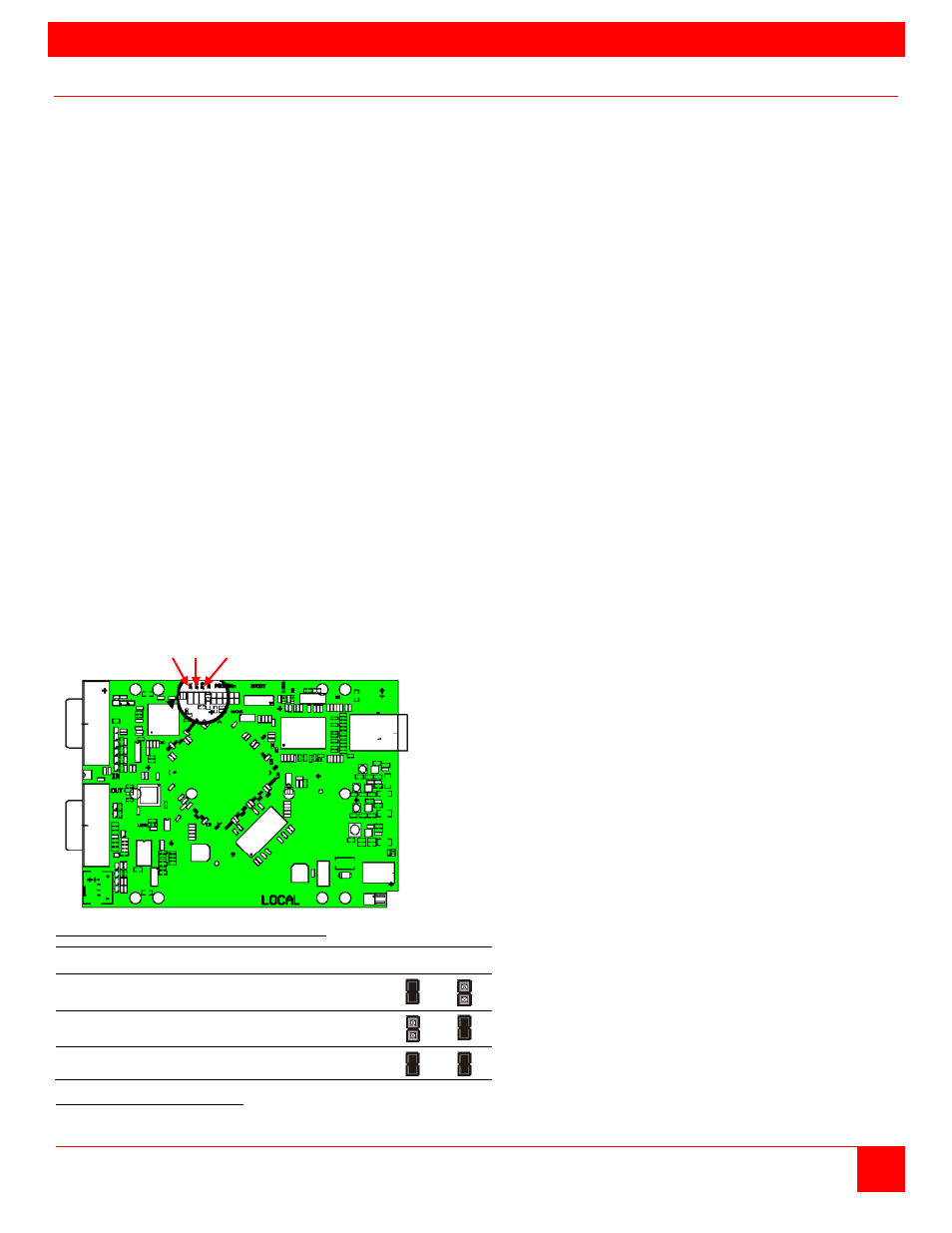
To modify the source of the DDC information, jumper JP1 and/or JP2 need to be re-positioned to designate the
DDC source as shown in Table 2. To change the jumper settings, first remove power from the Transmitter
unit. Next, remove the screws on the bottom and sides of the Transmitter chassis and carefully remove the top
of the chassis exposing the circuit boards. Locate the jumpers JP1 and JP2 as shown in figure 8.
Note: The four circuit boards each have JP1 and JP2 jumpers that can be changed.
JP1 / JP2 / JP3
Figure 8. Jumper Settings (Transmitter unit)
DDC Source
JP1
JP2
From Internal DDC Table (default setting)
From Local Monitor
From Remote Monitor
Table 2. DDC Source Settings