Operation, Operating instructions – local kvm access, Ddc information – Rose Electronics CrystalView DVI CATx User Manual
Page 17
OPERATION
CRYSTALVIEW DVI CATx INSTALLATION AND OPERATIONS MANUAL
11
Operating instructions – Local KVM access
Operation of your computer is no different than having your keyboard,
monitor, and mouse connected directly to the computer. All functions,
applications, upgrades and other items can be done normally. The only
difference is the computer can be up to 450 feet away.
CrystalView DVI CATx with local KVM access allows an additional KVM
station to be connected to the transmitter. The CPU can easily be operated
from the remote KVM station or the local KVM station but not simultaneously.
The transmitter or local unit is active during boot-up and the connected CPUs
video is displayed on both the local and remote KVM stations monitor. To
activate the remote KVM station, simply press any key on the remote KVM
stations keyboard. Control is passed to the remote KVM station. To activate
the local KVM station, press any key on the KVM station’s keyboard.
The dual video models have the capability of connecting the transmitter to two
video sources. The two video sources are sent to the receiver and displayed
on its two video monitors. Video source one should be connected to the
computer’s primary DVI video port that is associated with the keyboard and
mouse.
DDC Information
By default, the CrystalView DVI CATx uses its own internal DDC table. In
some configurations it may be necessary to redefine the source of the DDC
information. The CrystalView DVI CATx can use the internal DDC table, the
DDC information from the local video, or download the DDC information from
the remote video monitor. To modify the source of the DDC information,
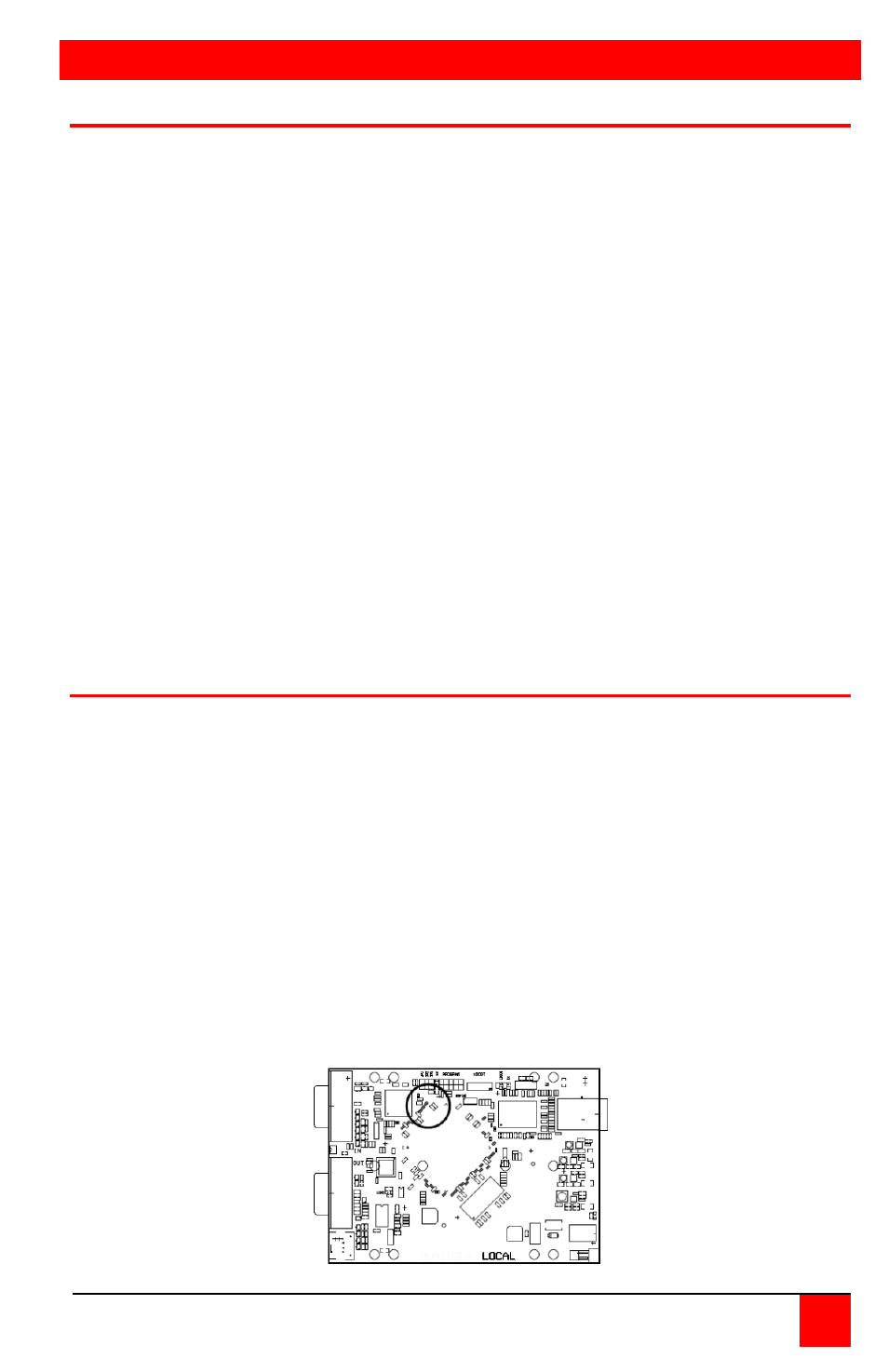
perform the following internal adjustments to the local unit. Adjustments are
made on the local unit to use the default DDC information, the LOCAL
monitor’s DDC information, or the REMOTE monitor’s DDC information.
A- Carefully remove the four (4) Phillips screws from the bottom of the
unit. If your model is a dual version, also remove the UNC screws that
secure the video connectors.
B- Remove the top cover exposing the internal PC board as shown
below
CAT5 Connector