Installation – Rose Electronics CrystalView USB2 User Manual
Page 8
INSTALLATION
4
CRYSTALVIEW USB2 INSTALLATION AND OPERATINS MANUAL
Installation
Please refer to the safety section first before proceeding with any
installation or configuration or the CrystalView USB2. It is recommended
that the following installation procedure be followed to assure proper cable
connections, power up sequencing, and accurate monitor DDC table
information is obtained from the connected video monitors. Also all
equipment should be powered off until all cabling is connected.
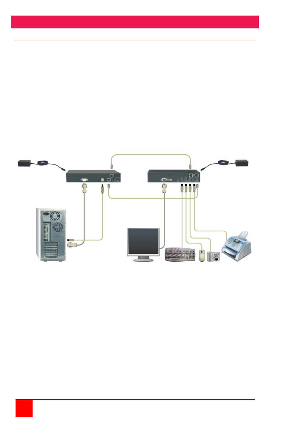
Figure 1 shows a typical configuration using the single video model. The
dual and quad video models are installed and configured in the same
manor with 2 or 4 PC video ports connected to the transmitter unit and 2 or
4 video monitors connected to the receiver unit.
USB 2.0 Host PC Monitor < < < USB Devices > > >
Figure 1 - Typical Configuration
NOTE: The maximum length of the Category 5 UTP cable must not
exceed 50m. If Cat-5 patch cable is used, total length should not
exceed 10m (EIA/TIA-568 specification).
NOTE: All references to Category 5 UTP solid core cable in this document
represent the minimum requirement. Category 5E, Category 6 or
better UTP or STP cable may be substituted.
NOTE: All units in the system should be tied to a common
EARTH ground for proper operation
Power Up to 150 feet of CAT5 cable Power
Adapter Adapter
Transmitter Receiver
Up to 150’ CAT5 cable
V
ideo C
abl
e
US
B
Ca
b
le