MEDC PH1 User Manual
Page 4
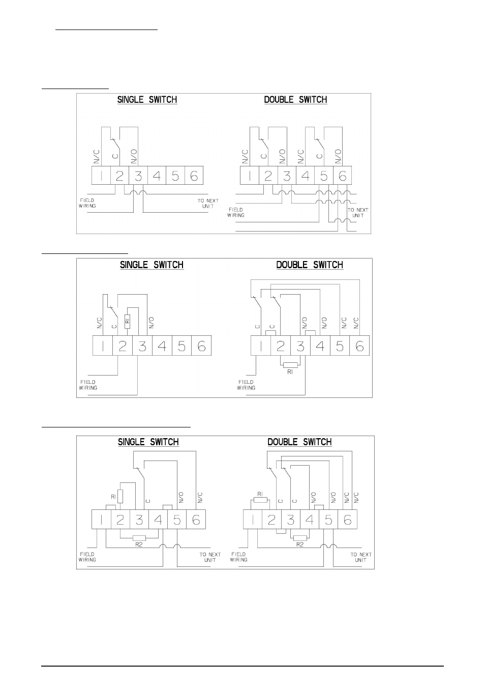
4.0 STANDARD WIRING OPTIONS
See below for various wiring options for the PH1. Note: This is not an exhaustive list and the units may be wired
to suit customer’s requirements. If a different wiring layout has been specified when ordering the unit, please see
separate wiring diagram supplied with the unit.
EOL resistors should only be fitted to the last unit in a system
Wiring - Switch only
Wiring – c/w EOL resistor
R1 – EOL Resistor
Wiring – c/w series or series & EOL resistors
R1 – Series resistor, R2 – EOL resistor (if fitted)
08/13
© Cooper MEDC 2013
See also other documents in the category MEDC Sensors:
- PB (8 pages)
- PB (32 pages)
- PB (24 pages)
- BG3 (8 pages)
- BG2 (12 pages)
- PB (12 pages)
- PH1 (20 pages)
- PAS1 (4 pages)
- SM87BG (28 pages)
- SM87BG (28 pages)
- XB13 Flashing Beacon (8 pages)
- SM87HXB (28 pages)
- FB11UL (4 pages)
- Expertline (16 pages)
- FB11 (20 pages)
- FB12 (20 pages)
- XB4 (24 pages)
- FB15 (4 pages)
- FB15 (16 pages)
- FL12 (20 pages)
- FL11 (20 pages)
- SM87 LU3 (24 pages)
- LD15 (32 pages)
- XB12 (20 pages)
- XB11 (24 pages)
- SM87LED (20 pages)
- XB10 (20 pages)
- XB12 (20 pages)
- XB13 (2 pages)
- XB15 (24 pages)
- XB15 (32 pages)
- XB16 (8 pages)
- XB9 (16 pages)
- XB8 (20 pages)
- dSLB 20 (4 pages)
- dSLB 20 LED (8 pages)
- DB1 (8 pages)
- PAS2 (4 pages)
- PAS2 (4 pages)
- DB1 (20 pages)
- HD1 Range (4 pages)
- HD1 Range (24 pages)
- CU1 (36 pages)
- JB11 (4 pages)