Fig. 2 fig. 3, Fig.3, Fig.2 – Medal Sports BL17201 User Manual
Page 7: Electronic connections diagram
6
FIG. 2
FIG. 3
FIG.3
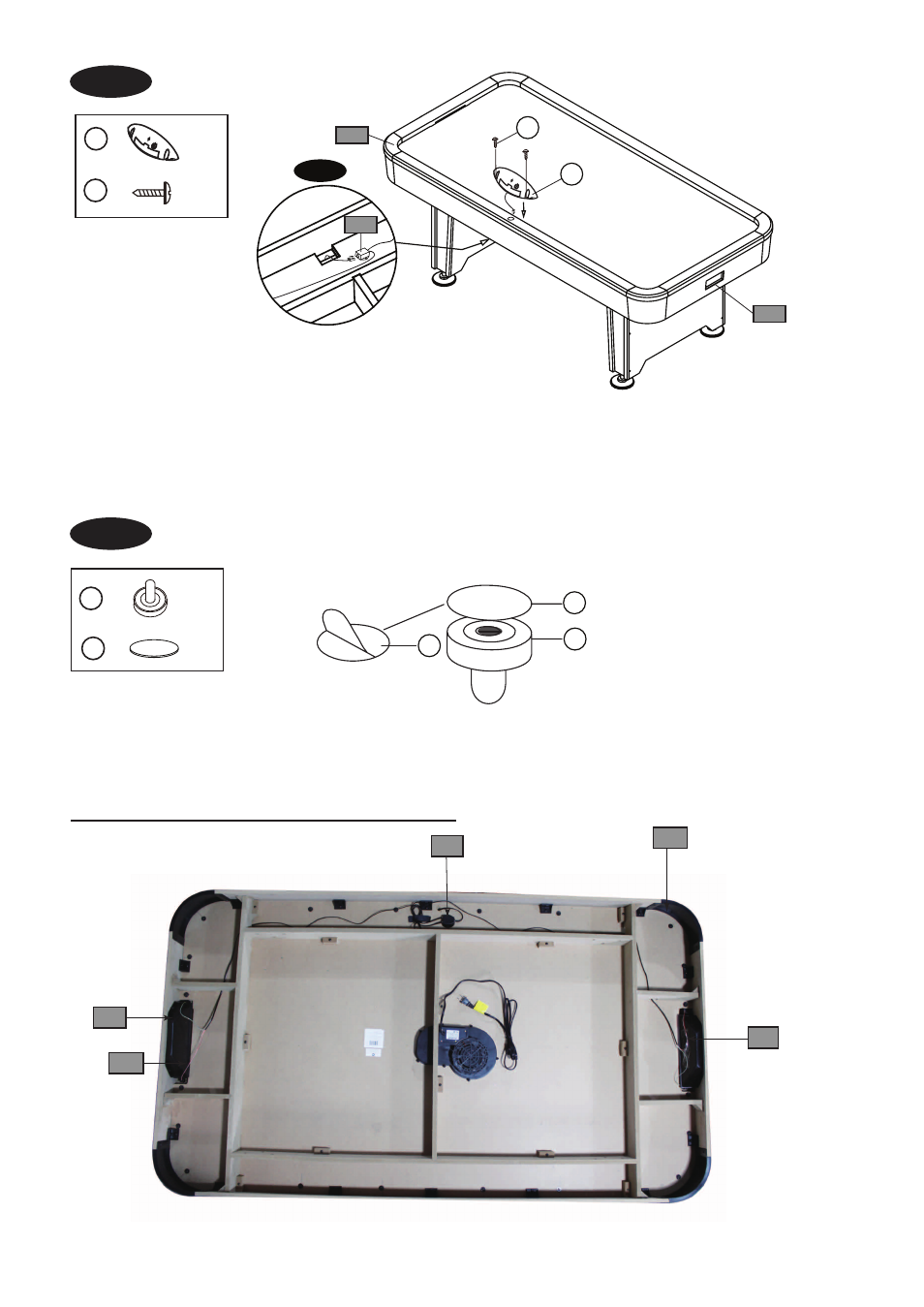
9. Tear off the backside paper of the Felt Pad (#8) and stick them at the bottom of the Pushers (#6).
See FIG.3.
FIG.2
7. Attach the Scorer (#9) to the top rail of the Main Cabinet (#1) using two Screws (#A5).
See FIG.2 .
8. Thread the Scorer Wire through the hole of the side apron to Insert the Scorer Wire into the Connect
Box (#P4).
See FIG.2 & 2A.
P4
P6
P7
P7
P2
X 2
X 1
9
A5
X 2
6
X 2
8
P3
P5
A5
9
P4
FIG. 2A
8
6
8
Electronic Connections Diagram
This manual is related to the following products:
See also other documents in the category Medal Sports Games:
- YSLSUIG3002 (15 pages)
- BL12408-14 (19 pages)
- BL12408-14 (10 pages)
- BL12408-14 (7 pages)
- SH16602 (17 pages)
- SH1312405 (7 pages)
- WMUS1314811 (11 pages)
- SH1416005 (12 pages)
- SH1318429 (14 pages)
- WMUS1312403 (6 pages)
- SMUS1318425 (15 pages)
- CS1319002/766281 (15 pages)
- BL12408-14 (7 pages)
- FH17201 (8 pages)
- BL18427-14 (11 pages)
- FH1438410 (7 pages)
- SMUS1418431 (12 pages)
- WM domestic 1412001 (7 pages)
- FH1414817 (9 pages)
- FH1412407 (7 pages)
- SH1339017 (14 pages)
- FH1438410 (10 pages)
- SH1416005 (12 pages)
- SH1418433 (15 pages)
- WMUSA1395300 (12 pages)
- SH51500 (13 pages)
- AM1351505 (8 pages)
- SH1358110 (15 pages)
- SH58403 (27 pages)
- 58102 (25 pages)
- SH58101 (21 pages)
- SMUS1351502 (9 pages)
- SH57001 (21 pages)
- SH1358412 (10 pages)
- SMUS1358406 (17 pages)
- CS.COM1358413/788598 (18 pages)
- BL58409 (18 pages)
- AM1351500 (7 pages)
- BL51803-14 (6 pages)
- BL58410 (10 pages)
- SM.Com1451511 (8 pages)
- SMUS1451509 (10 pages)
- SMPR1458416 (17 pages)
- WMC1451502 (9 pages)