Emerson, Air comfort products, Repair parts listing – Emerson CF715PW00 User Manual
Page 8: Trouble shooting, How to order repair parts
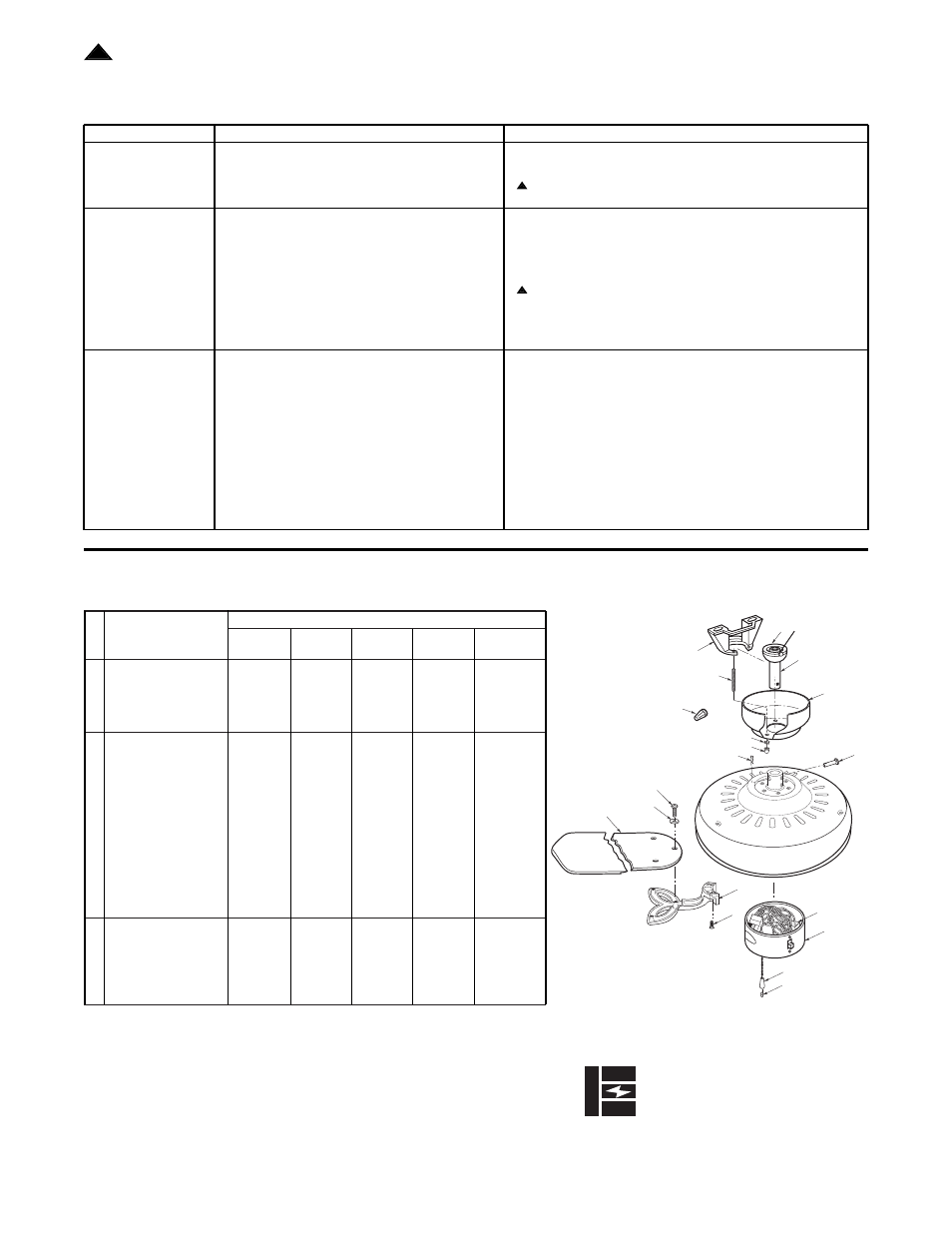
Repair Parts Listing
Part Numbers
Key
Model No.
Model No.
Model No.
Model No.
Model No.
No. Description
CF715AW
CF715AB
CF715PW
CF715WB
CF715S
*
Hanger Ball Assembly,
761655-21
761655-3
761655-22
761655-20
761655-16
Consisting of:
1
Hanger Bracket
—
—
—
—
—
2
Hanger Ball
—
—
—
—
—
3
Downrod
—
—
—
—
—
*
Parts Bag Containing:
761442-1
761442
761442
761442
761442
4
Wire Connector (3)
—
—
—
—
—
5
Threaded Stud (2)
—
—
—
—
—
7
Lockwasher (2)
—
—
—
—
—
8
Knurled Knob (2)
—
—
—
—
—
9
Coupling
—
—
—
—
—
10 Pin, Clevis
—
—
—
—
—
11 Clip, Hairpin
—
—
—
—
—
13 Wood Pendant
—
—
—
—
—
15 Screw, 1/4-20 x 1/2” (11)
—
—
—
—
—
18 Screw, 3/16-24 x 5/16”
Washer Head (16)
—
—
—
—
—
19 Washer, Blade (16)
—
—
—
—
—
6
Ceiling Canopy
760169-32
760169-2
760169-33
760169-30
760169-25
12 Wiring Harness
761947-1
761947
761947
761947
761947
14 Switch Housing
761919-16
761919
761919-17
761919-3
761919-2
16 Flange (set of 5)
761994-7
761994-8
761994-9
761994-7
761994-8
17 Blade (set of 5)
762162
762162-1
762162-2
762162-3
762162-4
— Owner's Manual
BP7249
BP7249
BP7249
BP7249
BP7249
Before discarding packaging material, be certain all parts have been
removed.
HOW TO ORDER REPAIR PARTS
WHEN ORDERING REPAIR PARTS, ALWAYS GIVE THE FOLLOWING INFORMATION:
• PART NUMBER
• NAME OF ITEM
• PART DESCRIPTION
• MODEL NUMBER
The model number of your Fan will be found on a label attached to the top housing.
For repair parts, phone 1-800-654-3545.
EMERSON
Air Comfort Products
DIVISION OF EMERSON COMPANY
8100 W. Florissant, St. Louis, MO 63136
Part No. F40BP72490000
Printed in Taiwan 11/00
Form No. BP7249
Trouble Shooting
TROUBLE
PROBABLE CAUSE
SUGGESTED REMEDY
1. Fan will not start.
1. Fuse or circuit breaker blown.
1. Check main and branch circuit fuses or circuit breakers.
2. Loose power line connections to the fan, or loose
2. Check line power connections to fan and switch wire
switch wire connections in the switch housing.
connections in the switch housing.
WARNING:
Make sure main power is turned off.
3. Reversing switch in neutral position.
3. Make sure reversing switch position is all the way to one side.
2. Fan sounds noisy.
1. Blades not attached to fan.
1. Attach blades to fan before operating.
2. Screws securing fan blade flanges to motor
2. Check to make sure the screws which attach the fan flanges to the
are loose.
motor are tight.
3. Wire connectors inside switch housing rattling.
3. Check to make sure wire connectors in switch housing are not
rattling against each other or against the interior wall of the switch
housing.
WARNING:
Make sure main power is turned off.
4. Motor noise caused by solid-state variable
4. Some fan motors are sensitive to signals from Solid-State variable
speed control.
speed controls. If Solid-State Control is used and motor noise
results choose an alternative control method.
5. Screws holding blades to flanges are loose.
5. Tighten screws securely.
3. Fan wobbles
1. Setscrew in motor coupling is not tightened
1. Tighten the setscrew in the motor coupling securely.
excessively.
securely.
2. Setscrew in the hanger ball/downrod assembly is
2. Tighten the setscrew in the hanger ball/downrod assembly.
loose.
3. Screws securing fan blade flanges to motor are loose.
3. Check to be sure screws which attach the fan blade flanges to the
motor are tight.
4. Fan blade flanges not seated properly.
4. Check to be sure the fan blade flanges seat firmly and uniformly to
the surface of the motor. If flanges are seated incorrectly, loosen
the flange screws and retighten according to the procedure in the
section on "How to Put Your Ceiling Fan Together".
5. Hanger bracket and/or ceiling outlet box is not
5. Tighten the hanger bracket screws to the outlet box, and/or secure
securely fastened
outlet box.
6. Fan blades out of balance.
6. Interchanging an adjacent (side-by-side) blade pair can redistribute
the weight and result in smoother operation.
WARNING:
FOR YOUR OWN SAFETY TURN OFF POWER AT FUSE BOX OR CIRCUIT BREAKER
BEFORE TROUBLE SHOOTING YOUR FAN.
17
16
14
19
18
13
9
11
10
6
4
8
5
7
1
2
3
15
12
!
!
!