Operation, Adjusting the anti-scalp rollers – Exmark Turf Tracer x-series LP FMD524 User Manual
Page 22
Operation
Figure 7
Left Hand Side Shown
Adjusting the Anti-Scalp Rollers
It is recommended to change the anti-scalp roller
position, when the height of cut has changed.
1. Stop the machine and move the motion control
levers outward to the neutral locked position.
2. Disengage the PTO.
3. Engage the park brake.
4. Stop the engine, remove the key and wait for all
moving parts to stop.
5. After adjusting the height of cut, adjust the
anti-scalp rollers by removing the whizlock nut
and spring disc washer.
6. Adjust the anti-scalp rollers for Normal Operating
Conditions. Place the rollers in one of the
positions shown (Figure 8). Rollers will maintain
3/4 inch (19 mm) clearance to the ground to
minimize gouging and roller wear or damage.
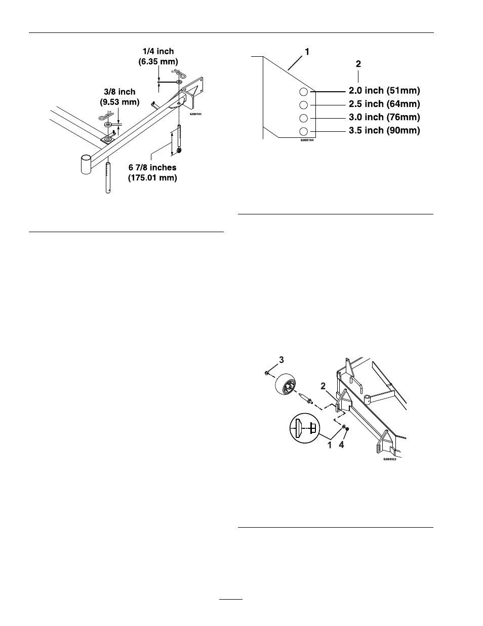
Figure 8
For cutting heights above 3.5 inches (90 mm) use the
bottom hole. The rollers will still be effective against
scalping.
1.
Anti-scalp roller
mounting bracket
2.
Cutting height
For Maximum Deck Flotation, place the rollers
one hole position lower. Rollers should maintain
1/4 inch (6.4 mm) clearance to the ground. Do
Not adjust the rollers to support the deck.
7. Be sure the whizlock nuts are installed with the
spring disc washer between the flange of the nut
and the mounting bracket.
8. Torque the 3/8–16 whizlock nut to 30-35 ft-lb
(41-47 N-m) (Figure 9).
9. If the 3/8 nyloc nut has been removed, reinstall
and torque to 30–35 ft-lb (41-47 N-m).
Figure 9
1.
Spring disc washer
(cone towards nut)
3.
3/8 nyloc-torque to 30-35
ft-lb (41-47 N-m)
2.
Front right anti-scalp
bracket shown
4.
3/8-16 whizlock nut
torque to 30-35 ft-lb
(41-47 N-m)
22