Fig.7 fig.6, Fig.9 fig.8 – Sealey SPB27W User Manual
Page 3
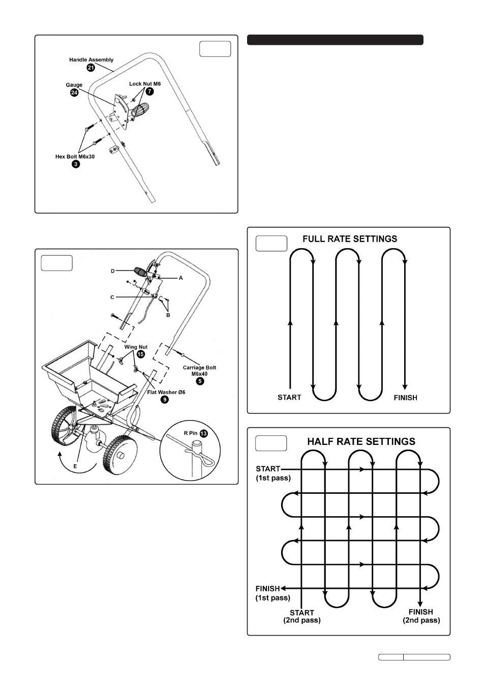
5. OPERATION
5.1 The spreader is designed to be pushed at three miles an hour,
which is a brisk walking pace. Slower or faster speeds will
change the spread pattern. Wet fertiliser will also change the
spread pattern.
5.2 use the Stop bolt on the gauge to ensure the same amount of
distribution.
5.3 See figs.8 & 9 for suggested walking patterns depending on
the level of coverage you require.
5.4 Always start walking prior to opening the flow control plate.
5.5 Every time you are ready to stop, or turn to make a new pass,
close the flow control plate to stop dispensing the material and
continue one more stride. This reduces waste and avoids
damaging a lawn with over saturated product coverage.
5.6 To ensure consistent coverage, make sure each broadcast
pattern slightly overlaps the previous one.
5.7 Make sure that any broadcast material does not come into
contact with trees, shrubs and flowers that could be harmed by
the material.
5.8 Clean the spreader thoroughly after each use paying particular
attention to the shut off plate and the bottom of the hopper.
Original Language Version
SPB27W Issue: 1 - 21/06/11
fig.7
fig.6
4.6 Refer to fig.6.
4.6.1 Attach the gauge and lever assembly (24) to the inside of the
handle assembly (21). Secure with M6x30 hex bolts (3) and M6
lock nuts (7).
4.7 Refer to fig.7.
4.7.1 Slide the handle assembly around the support leg assembly
and secure with carriage bolts (5), flat washers (9) and wing
nuts (15).
4.7.2 Insert the bent end of the control clamp wire into the small hole
in the lever assembly (A).
4.7.3 Remove the hex bolt from cable clamp then insert the control
cable into the clamp (B,C).
4.7.4 Re-insert hex bolts to clamp control cable in place.
4.7.5 Move the lever (D) down to open the spreader slots in the
bottom of the hopper. If the holes are not fully exposed, loosen
the cable clamp (C) and adjust the cable.
4.7.6 Insert R-pin (13) through top of the vertical axle.
fig.9
fig.8