Fig.2 fig.3 fig.5 fig.4, Fig.4, Fig.1 – Sealey SPB27W User Manual
Page 2
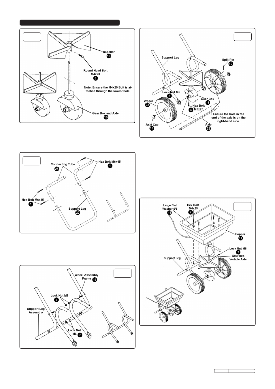
4.2 Refer to fig.2.
4.2.1 Insert the connecting tubes (25) into the support leg (20) and
hold with hex bolt M6x45 (1).
4.2.2 Insert the other two hex bolts M6x45 (1) through the middle
holes in the connecting tubes, ready for step 3.
4.3 Refer to fig.3.
4.3.1 Slide the wheel assembly frame (19) over the bolts already in
the support leg assembly. Secure with 4 M6 lock nuts (7).
fig.2
fig.3
fig.5
fig.4
4.4 Refer to fig.4.
4.4.1 Slide the axle (23) through one wheel (22), frame and gearbox,
through the other leg of the frame and then the other wheel.
4.4.2 Looking at the spreader from the front, ensure the axle (23) is
inserted from the left, so that the hole in the end of the axle
(23) lines up with the hole in the right hand side wheel.
4.4.3 Secure the right hand wheel (22) to the axle (23) with the split
pin (12).
4.4.4 Attach the axle (23) to the gear box with the M5 hex bolt (4)
and lock nut (8).
4.4.5 Insert axle caps (14) into the middle of the wheels (22).
fig.4
4.5 Refer to fig.5.
4.5.1 Lower the hopper (17) over the axle and onto the frame and
secure with 4 hex bolts (2), large flat washers (11) and lock
nuts (7).
Note! Before assembly ensure there are no missing parts or fixtures.
4.1 Refer to fig.1.
4.1.1 Slide the Impeller (18) over the vertical axle on the gear box (16).
4.1.2 Secure the Impeller to the axle with a round head bolt M4x20 (6).
fig.1
Original Language Version
SPB27W Issue: 1 - 21/06/11
4. ASSEMBLY