Figure 6-6 – EFJohnson 764X User Manual
Page 64
ADJUSTMENT PROCEDURE
6-9
November 1998
Part No. 001-7600-001
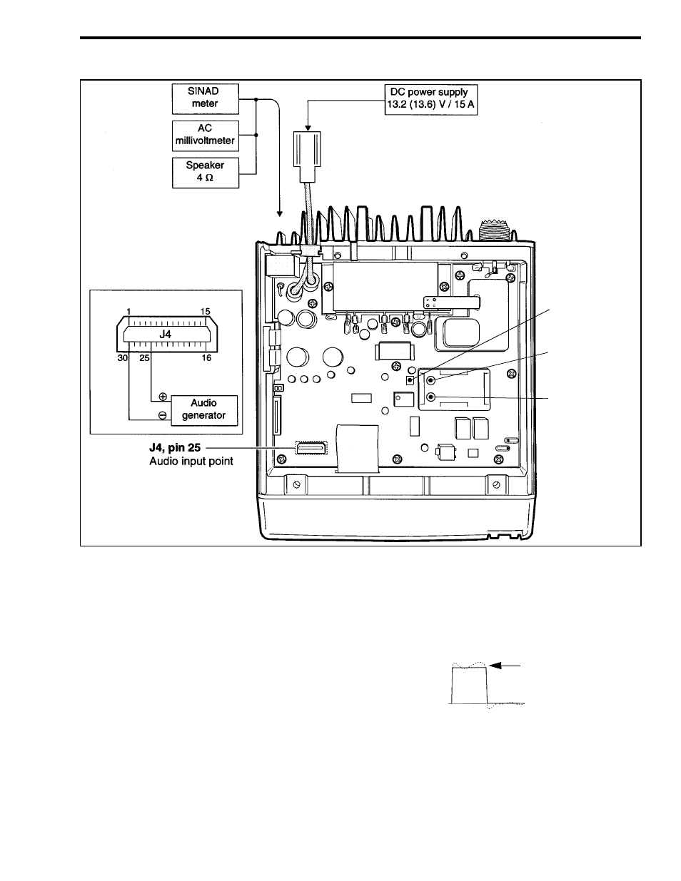
Figure 6-6 UHF Adjustment Points
6.7.4 DTCS WAVEFORM ADJUST
1. Select the channel on the low end of the pro-
grammed for DTCS code 007N (Test Ch. 5).
2. On the computer screen, scroll to “DTCS N” if set-
ting a narrow band channel or “DTCS W” if setting
a wideband channel.
3. Key the transmitter and view the demodulated sig-
nal on the CRT of a communications monitor.
4. Press the adjust keys on the computer so that the
waveform appears as follows:
5. If the transceiver operates on both narrow and wide
band channels, select Test Ch. 7 and also set the
waveform on that channel (see note in Table 6-2).
L23
PLL lock voltage
adjustment
CP1
PLL lock voltage
check point
L26
PLL lock voltage
adjustment
Set For
Flat
Waveform
UHF ADJUSTMENTS (CONT’D)