Electric clutch adjustment, Figure 30, Maintenance – Exmark Lazer Z 4500-872 User Manual
Page 41: Warning
Maintenance
Figure 30
1.
2 inch height of cut location
E. Start the mower while in the operator position.
WARNING
Engine must be running and drive wheels
must be turning so adjustments can be
performed. Contact with moving parts or
hot surfaces may cause personal injury.
Keep fingers, hands, and clothing clear of
rotating components and hot surfaces.
F. Release the park brake so the handle rests on
the 1/2 x 6 inch rod or bolt.
G. Move the throttle to high idle.
H. Move both motion control levers to the full
forward position and hold for 15 seconds.
I. Move both motion control levers to the full
reverse position and hold for 15 seconds.
J.
Turn off the engine and completely release
the park brake by removing the 1/2 x 6 inch
rod or bolt.
K. Allow the hubs to cool until they are cool
enough to safely touch.
L. Rotate the drive wheel release handle to the
“released” position. Refer to the Drive Wheel
Release Valves section in Operation.
M. Readjust both brakes following the procedure
18. Rotate the drive wheel release handle to the
“operating” position. Refer to the Drive Wheel
Release Valves section in Operation.
19. Install the rear tires and torque lug nuts to 90-95
ft-lb (122-129 N-m).
20. Remove jack stands.
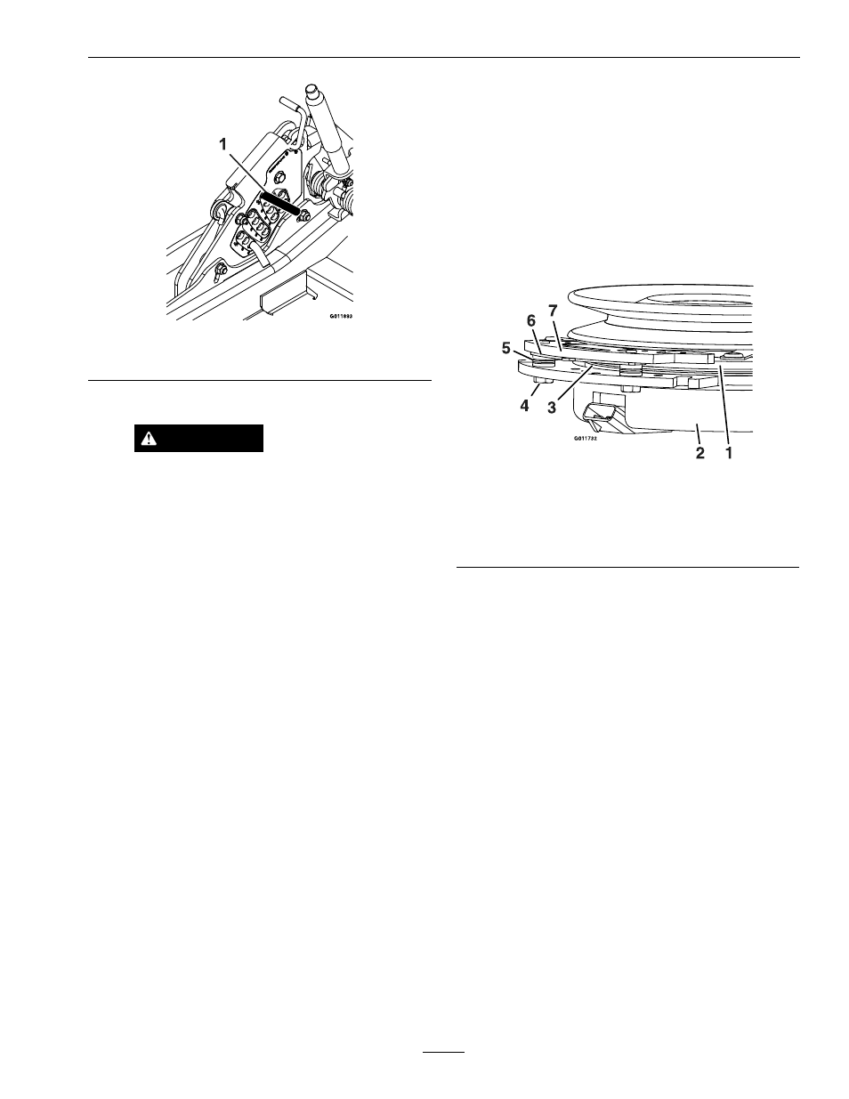
Electric Clutch Adjustment
No adjustment necessary. However on units with 60
inch decks, when the clutch brake has worn to the
point where the clutch no longer engages consistently,
the shim can be removed to extend the clutch life.
Figure 31
1.
Armature
5.
Brake spacer
2.
Field shell
6.
Re-gap shim
3.
Rotor
7.
Brake pole
4.
Brake mounting bolt
Removing the Shim:
1. Stop engine, wait for all moving parts to stop,
and remove key. Engage parking brake. Allow
the machine to cool completely before starting
these instructions.
2. Using a pneumatic line, blow out any debris
from under the brake pole and around the brake
spacers.
3. Check the condition of the wire harness leads,
connectors, and terminals. Clean or repair as
necessary.
4. Verify that 12V is present at the clutch connector
when the PTO switch is engaged.
5. Measure the gap between the rotor and armature.
If the gap is greater than .04 inch (1 mm), proceed
with the following steps:
A. Loosen both brake mounting bolts one-half
to one full turn (see Figure 32).
Note: Do Not remove the brake pole from
the field shell/armature. The brake pole has
worn to match the armature and needs to
41