Om_m150-2.pdf, Wiring diagram esquema de cableado – Essick Air M150 User Manual
Page 3
CAUTION: To reduce the risk of fi re or electrical
shock, do not use this fan with any solid state speed
control device.
Select the area you wish to cool. Evaporative coolers
work best near a partially opened door or window to
draw in fresh air. An equal amount of air should be
discharged out of the room to dispel heat and humidity.
Fill the reservoir from the back. The reservoir holds
5 1/2 gallons of water. DO NOT OVER FILL. Water
will leak out and could cause water damage to the sur-
rounding area. If the reservoir runs dry, it will not harm
the pump. When transporting the unit to a different
location, be very careful not to spill the water. It is best
to re-locate the cooler, and then add water.
Included is a fl oat for continuous fi ll. To attach the
fl oat, remove the back grille. Remove the nuts from
the fl oat and insert the fl oat into the water shield and
then through the hole in the housing. Secure the fl oat
with the nut that was removed. You may connect ei-
ther a 1/4 inch hose or a garden hose using the garden
hose adapter. Adjust the fl oat so that the water level is
about an inch below the top of the reservoir. Reinstall
the back grille.
Plug the electrical cord into a 115-120 volt grounded
outlet. You may operate your cooler on one of three
speeds: low, medium or high. Turn the switch knob
clockwise to activate the pump and fan. This will cool
the air. Turn the switch counterclockwise to operate
the cooler as a fan only (pump will be off).
Unpack your cooler and install the casters. Slip the
stems of the casters into the holes provided in the bot-
tom of the front and back grille.
CAUTION: To reduce the risk of fi re, always unplug
the cooler before attempting service of any kind.
No oil or lubrication is necessary. The motor is perma-
nently lubricated at the factory.
No oil or lubrication is necessary. Clean any debris
from under the pump in the inlet area.
Remove the fi lter from the rear grille and rinse with
water. Be careful not to damage the fi lter! The fi lter
should be replaced every two years or if it becomes
clogged.
Drain and clean the water tank. To drain, remove the
back grille and disconnect the clear hose from the
black tube. Turn unit on cool and pump out most of
the water. Wipe dry and clean with a towel. Before
reattaching the back grille, reconnect the clear hose to
the black water tube.
CAUTION: Always unplug the cooler before attempt-
ing service of any kind.
POSSIBLE CAUSE/REMEDY:
1. The pump hose may have worked loose. Check the
connection at the pump and at the water tube located
in the back grille assembly. Reconnect pump hose if
necessary.
2. The water tube may be blocked. Remove the tube
and clean it out. Make sure water holes are clear.
3. The pump or switch may be defective. Replace
pump or switch, if necessary.
POSSIBLE CAUSE/REMEDY:
1. Verify there is 115-volt power at the electrical outlet.
Check the fuse or breaker.
1. The fan switch or motor may be defective. Replace
if necessary.
PROBLEM:
Cooler Does
Not Pump
Water
PROBLEM:
Fan Does Not
Operate
This warranty is extended to the original purchaser
only. It does not cover damages incurred during
shipping or through accident, neglect, or abuse by the
owner. Essick Air Products/Champion Cooler does not
authorize any person or representative to assume any
other or different liability in connection with this cooler.
All original parts provided by Essick Air Products/
Champion Cooler are warranted against defects in
material or factory workmanship for one year.
Essick Air Products/Champion Cooler is not respon-
sible for incidental or consequential damage resulting
from any malfunction.
Essick Air Products/Champion Cooler is not respon-
sible for any damage occurring from the use of water
softeners, chemicals, de-scale material, or if a higher
horsepower motor is used in the unit other than what
Essick Air Products recommends.
Essick Air Products/Champion Cooler is not respon-
sible for the cost of service calls to diagnose cause of
trouble, or labor charge to repair and/or replace parts.
Contact the Dealer where you purchased the evapora-
tive cooler. If for any reason you are not satisfi ed with
the response from the Dealer, contact the Customer
Service Department: Essick Air Products, 5800
Murray Street, Little Rock, Arkansas 72209 or call 800-
643-8341.
Register your product online at:
www.essickair.com/eac/onlineregistration-eac.htm
Terms And
Conditions
Of Warranty
Exclusions
From
Warranty
How To
Obtain
Service
Under This
Warranty
Register
Product
Motor
Pump
Filter
Water Tank
MAINTENANCE
LIMITED WARRANTY
TROUBLE SHOOTING
EVAPORATIVE COOLER
OPERATION
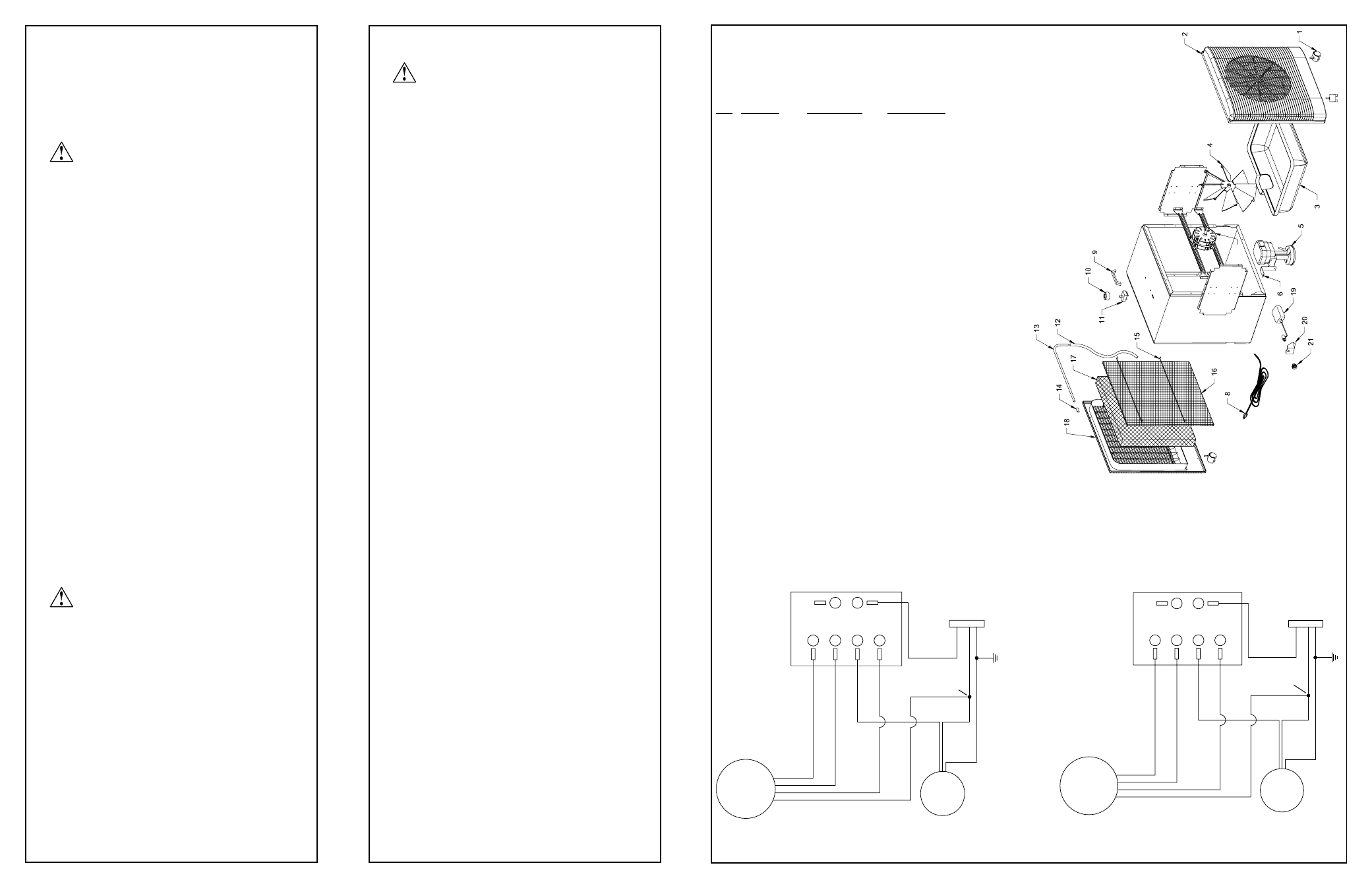
REPLACEMENT PARTS LIST
LISTA DE PIEZAS DE RECAMBIO
MOTOR
RED
BLACK
BLUE
WHITE
4
WHITE /
RIBBED
(COMMON)
BLACK /
SMOOTH
(HOT)
PUMP
3
2
A
B
1
RIBBED
SUPPLY
SMOOTH
115V
GREEN
3 SPEED
SWITCH
GREEN (GROUND)
WIRE NUT OR
CRIMP TERMINAL
DE 115V
MOTOR
BLANCO
AZUL
NEGRO
ROJO
4
NEGRO / LISO
BOMBA
2
3
1
LISO
VERDE
ACANALADO
INTERRUPTOR DE
3 VELOCIDADES
B
A
ABASTECIMIENTO
BLANCO /
ACANALADO
VERDE (TIERRA)
EMPALME PLASTICO
7
1 110822-4 Casters
Ruedecilla
(4 req’d)
(4 req’d)
2 110845-22 Front
Grille
Rejilla
Anterior
3 110850-2 Reservoir
Depósito
De
Agua
4 110846-2 Fan
Blade
Hoja
De
Ventilador
5 110438
Pump
Bomba
6
224135-001
Pump Mount
Soporte De La Bomba
7 110441-4 Motor
Motor
8
110394-2
Power Cord
Cable De Corriente
9 110849-2 Handle
Asidero
10 110845-24 Knob
Perilla
11 110425-1
Switch
Interruptor
12 310718-1
Hose
Manga
13 110588-1
Tube
Tubo
14
110721
Tube Cap
Tapa Del Tubo
15
155001-14
Pad Retainer
Soporte De Filtros
(2 req’d)
(2 req’d)
16
110121-1
Poly Pad
Filtro De Poliester
17 110122-1
Media
Medio
Evaporativo
18 110845-21 Back
Grille
Rejilla
Posterior
19 FL-C
Float
Flotador
20
110852
Water Shield
Salpicadero del Flotador
21 110824
Garden
Hose Adaptador
para
Adapter
Manguera De Jardín
No. Part
No.
Description
Descripción
WIRING DIAGRAM
ESQUEMA DE CABLEADO
Before
Operation
Fill Reservoir
Float
Installation
Operation