Eicon Networks DN/I300TEPHMP User Manual
Dialogic, Dn/i300tephmp digital network interface board, Installation guide
Part number: 64-0083-02
Dialogic
®
DN/I300TEPHMP Digital
Network Interface Board
Installation Guide
Copyright © 2005-2007 Dialogic Corporation.
All rights reserved.
1. Product Description
The Dialogic
®
DN/I300TEPHMP Digital Network
Interface Board (“board”) is a high-density, high-
performance, network interface board in a universal
PCI form factor with one T1/E1 digital network
interface. This board is designed to be used with
Dialogic
®
Host Media Processing (HMP) software
(Release 2.0 or higher). The DN/I300TEPHMP
Digital Network Interface Board includes the
following components:
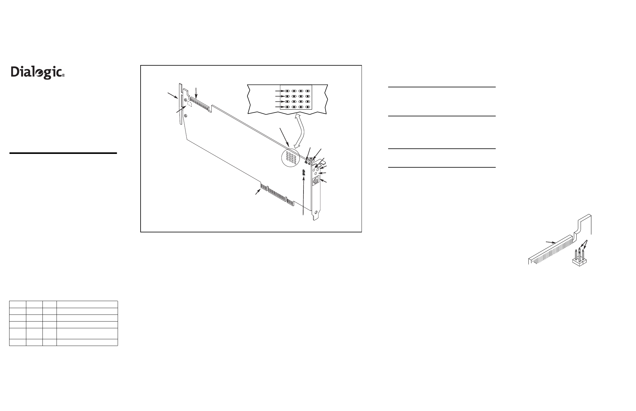
RJ-48C Jack: One connector to a T1 or E1 trunk.
General Network Interface Alarm LED: When lit,
indicates an alarm condition is present on the
trunk.
Reset LED: When lit, indicates that the board is in
the reset state.
Power LED: When lit, indicates power is on.
SW1: Rotary switch used to set board identification
(Linux system only).
Alarm/Status LEDs: A set of four LEDs for the
trunk. During power-up, the LEDs indicate Power
On Self Test (POST) status. After the board is
started, the green, yellow, and red LEDs indicate
normal operation or Carrier Failure Alarms (CFAs)
as shown in the following table. The Loopback
LED indicates when the trunk is in loopback
mode.
Green
Yellow Red
Conditions
ON
OFF
OFF
Normal Operation
OFF
OFF
ON
Loss of Signal (LOS)
ON
OFF
ON
Red Alarm
ON
ON
OFF
Yellow Alarm/Remote Alarm
Indicator (RAI)
ON
ON
ON
Alarm Indicator Signal (AIS)
CT Bus Connector: Connector to CT Bus.
Optional ISA Edge Retainer: Bracket used to
install board in an ISA form factor PCI slot.
P5: CT Bus Termination Jumper Block. Factory
default is unterminated. Signals must be
terminated only on boards at each end of an
optional CT Bus cable.
JP3X11 and JP4X11: Power-off Default Front End
Loopback for the trunk. Factory default is enabled
(jumper clips installed).
JP5: Boot up Default Front End Loopback. Factory
default is enabled (jumper clip removed).
Universal PCI Bus Connector: Connector to
universal PCI Bus slot.
Additional Information
Additional information about the DN/I300TEPHMP
Digital Network Interface Board is available from a
number of sources.
The product data sheet, available at
http://
www.dialogic.com/products/list.asp
, provides a
functional description as well as information about
applications and configurations, features, and
technical specifications.
Refer to the Release Guide and the online Release
Update for your Dialogic
®
Host Media Processing
(HMP) software release to verify that the DN/
I300TEPHMP Digital Network Interface Board is
supported in the release and for information on any
new features or issues that may relate to it.
The Regulatory Notices document that is packed
with each Dialogic
®
DN/I300TEPHMP Digital
Network Interface Board contains safety warnings
and national requirements for proper operation of
telecommunications equipment.
2. Before You Begin
Protecting the Board from Damage
CAUTION: All computer boards are sensitive to
electrostatic discharge (“ESD”). Handle all static-
sensitive boards and components at a static-safe
work area, and observe anti-static precautions at all
times.
If you are not familiar with ESD safety precautions,
visit http://dialogic.com/support/hwinstall to learn
more.
Unpacking the Board
CAUTION: Do not remove the board from the anti-
static packaging until you are ready to install it.
Observe proper anti-static precautions at all times.
Unpack the board according to the following steps:
1. Prepare a static-safeguarded work area.
2. Carefully remove the board from the shipping
carton and static-shielding bag. Handle the
board by the edges and avoid touching the
board's components.
3. Lay the board on the static-safe work surface.
Note: Place boards in static-shielding bags when
carrying boards from station to station.
Setting the Board ID
The device driver assigns board instance numbers
in ascending order (beginning with 0) as it detects
each board in your system. A board instance
number is the identification (ID) number used by the
Dialogic
®
Host Media Processing (HMP) software to
recognize the board.
Note: If you add or remove a board, the system
may change the existing board instance numbers,
depending on the PCI bus and slot number where
the board is installed or removed.
In a Windows system, leave SW1 (see Physical
Layout) set to the factory default of 0 to let the
system automatically assign board instance
numbers by PCI bus slot number. After the hardware
and the Dialogic HMP software are installed, refer to
the Dialogic
®
Configuration Manager (DCM) to
retrieve the assigned board instance ID number(s).
Dialogic
®
Configuration Manager (DCM) is a utility
that enables you to add new boards to your system,
start and stop system service, and work with board
configuration data. This utility can be accessed from
the Start menu in the Dialogic HMP software
program folder. For more information about board
identification, see the DCM online help.
In a Linux system, you must set SW1 to a unique
number for each installed board. Use a non-
magnetic screwdriver to turn SW1 to one of 16
board settings, 0–9 or A–F. After the hardware and
the Dialogic HMP software are installed, refer to the
proper configuration files to retrieve the assigned
board instance ID number(s). For more information
about Linux configuration files, see the Dialogic
HMP software release documentation.
Setting CT Bus Termination
This section applies if you are using a CT Bus cable
to connect your board to other boards in the system.
Bus signals are terminated when the CT Bus jumper
clip is installed. To terminate bus signals, install a
jumper clip on the pair of CT Bus termination pins
only on boards located at each end of the bus cable.
Factory default is unterminated (jumper clip
removed).
The following figure shows the pair of pins used for
CT Bus termination. Refer to P5 in the Physical
Layout figure for the location of the jumper block.
Setting Power-off Default Front End
Loopback
When the system shuts down (powers off), the
board enables analog loopback to the connected
trunk line. Factory default setting is enabled for the
trunk (jumper clips are installed). To disable, remove
the pair of jumper clips for the trunk.
The pair of jumpers for the trunk is JP3X11 and
JP4X11. Refer to the Physical Layout figure for the
location of the jumpers.
CT Bus
Termination
CT Bus
Connector
Physical Layout
RJ-48C Jack
General Network
Alarm LED
Universal PCI
Bus Connector
P5
(on reverse
side of board)
CT Bus
Connector
SW1
Optional ISA Edge
Retainer
Reset LED
Power LED
JP5
Alarm/Status LEDs
JP3X11
and JP4X11
Red
Yellow
Green
Loopback
1