Eicon Networks Dialogic Media Board DMV600BTEC User Manual
Dialogic, Dmv600btec media board, Before you begin
Dialogic
DMV600BTEC
Media Board
Quick Install Card
Part Number 64-0079-02
Copyright © 2003-2007
Dialogic Corporation.
All Rights Reserved.
Before You Begin
Protecting the Board from Damage
CAUTION:
All computer boards are sensitive to
electrostatic discharge (“ESD”). Handle all static-
sensitive boards and components at a static-safe
work area, and observe anti-static precautions at all
times.
If you are not familiar with ESD safety precautions,
more.
Unpacking the Board
Unpack the Dialogic
®
DMV600BTEC Media Board
(“board”) according to the following steps:
1. Prepare a static-safeguarded work area.
2. Carefully remove the board from the shipping
carton and anti-static packaging. Handle the
board by the edges and avoid touching the
board’s components.
3. Lay the board on the static-dissipative work
surface.
Note: Place boards in static-shielding bags when
carrying boards from station to station.
CAUTION: Do not remove the board from the anti-
static packaging until you are ready to install it.
Observe proper anti-static precautions at all times.
Installing the Hardware
Note: For a new installation, you should install the
hardware before installing the system software. If you
are adding boards to an existing system, there is no
need to uninstall or reinstall the software.
CAUTION: This document provides instructions for
installing the DMV600BTEC in a “cold” (power off)
system, most of which also apply to live insertion or
hot swap systems. It is important to note that there
are additional, system-dependent considerations for
live insertion. See the Administration Guide for your
Dialogic
®
System Software release for detailed
information on live insertion.
1. Work at a static-safe area. Turn the power to the
chassis OFF if you do not have a live insertion
system. If you have live insertion capability, the
power to the chassis can remain ON.
2. Remove the chassis cover plate or open the door
on both the front and back of the chassis.
3. Select an empty slot and remove the slot’s access
cover plates (if applicable).
Installing the Rear I/O Module
Note: If you are installing hardware in a live insertion
system with the power on, you should install the rear
I/O module before the baseboard.
4.
Install the I/O module in the rear of the selected
slot. Use the slot’s board guides as you insert the
board into the chassis slot. Make sure the tabs on
the board extractors engage the guide holes in the
chassis card cage, then lock down the board
extractors until the red locking tabs snap shut.
CAUTION: CompactPCI backplane pins are easily
bent. Make sure that the board connectors are
mating properly with hand pressure before fully
seating the board. When using the board extractors
to seat the board, make sure to seat evenly.
CompactPCI
Chassis (Rear)
Installing Rear I/O Module
Locked
Position
Unlocked
Position
Bac
kplane
Rear I/O
Module
Installing the Baseboard
Note: If you are installing hardware in a live insertion
system with the power on, you should install the rear
I/O module before the baseboard.
5. Install the baseboard in the front of the selected
slot. Use the slot’s board guides as you insert the
board into the chassis slot. Make sure the tabs on
the board extractors engage the guide holes in the
chassis card cage, then lock down the board
extractors until the red locking tabs snap shut.
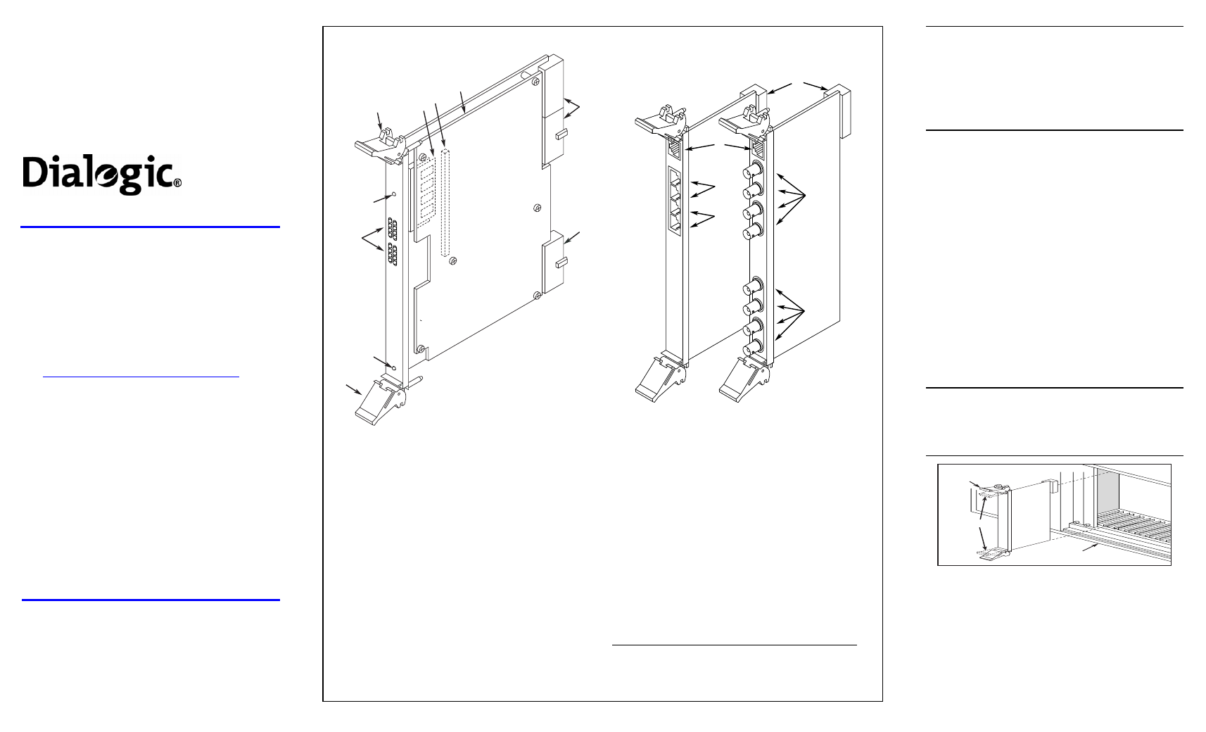
Physical Description
1
2
3
4
5
6
8
8
7
RE
D
YE
L
RE
D
YE
L
CA
RR
SG
NL
LO
OP
BA
CK
CA
RR
SG
NL
LO
OP
BA
CK
OUT O
F
SER
VIC
E
PO
W
ER
Com
pac
tP
CI
A
L
A
R
M
S
/
S
T
A
T
U
S
4
3
2
1
4
E
T
H
E
R
N
E
T
E
T
H
E
R
N
E
T
11
12
9
10
Not
Used
Not
Used
RJ48C
(T1 and 120-Ohm E1)
BNC
(75-Ohm E1)
J1
J2
R1
R2
T1
T2
CompactPCI Baseboard
Rear I/O Modules
1. Out of Service LED: Indicates board is out of service or
in reset from host.
2. Alarm/Status LEDs: During power-up, indicate Power
On Self Test (POST) status. During operation, the top
two sets of LEDs indicate status and alarms for the two
trunks (the bottom two sets of LEDs are unused):
Red–Indicates loss of clock on incoming line from
external network.
Yellow–Indicates loss of frame synchronization at far
end of external network.
Carrier Signal–Indicates board is powered up and
receiving signal from external T1 or E1 source.
Loopback–Indicates the T1 or E1 network is in loopback
mode.
3. Power LED
4. Board Extractor (with red locking tab)
5. Global Memory Module
6. Signal Processor Daughterboard connector
7. Signal Processor Daughterboard
8. J1, J4, J5: Board connector to CompactPCI backplane.
J1 key conforms to PICMG universal hot swap.
9. BNC Connectors (T1, R1, T2, R2,): Connectors to
external 75-Ohm E1 digital telephone network interfaces.
(Connectors T3, R3, T4, and R4 are not used in this
assembly.)
10. RJ48C Connectors (J1, J2): Connectors to external T1
or 120-Ohm E1 digital telephone network interfaces.
(Connectors J3 and J4 are not used in this assembly.)
11. Ethernet Connector: The Ethernet connectors are not
functional on this assembly.
12. J5: Rear I/O module connector to CompactPCI
backplane.
The default configuration of the Rear I/O Modules provides
loopback connection (signals to the board are looped back to
the source) when the board is powered off and during board
initialization. To disable loopback mode on either trunk,
remove the shunts from the indicated jumper pins:
RJ48C I/O module
BNC I/O module
Trunk 1
JP1 & JP2
JP100 & JP101
Trunk 2
JP3 & JP4
JP200 & JP201