Power supply continued, Installation – Eton E1 User Manual
Page 6
8
9
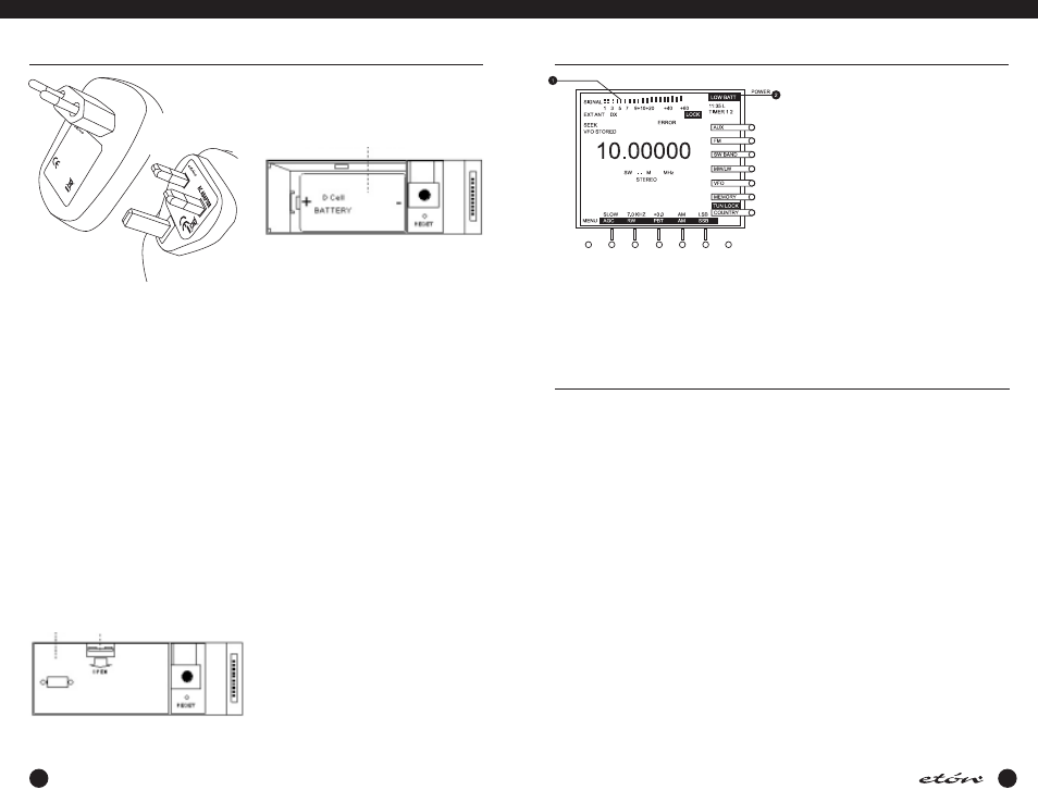
BATTERY CONDITION
Battery condition can be observed when the unit is
turned on or if the ‘LIGHT’ button is pressed if no AC
ADAPTER is connected to the receiver. W hen the
POWER key is pressed, or when the ‘LIGHT’ button is
pressed, a screen will be observed similar to the follow-
ing illustration during the first two seconds after depres-
POWER SUPPLY continued
E1
MANUAL
sion. After that time, the normal E1 display will be
observed.
(1) Battery Condition Graph - This bar graph shows the
relative charge of the batteries installed in the
receiver. You will note that on the left, there is an
“EMPTY” notation and on the right is a “FULL”
notation. A fully charged set of batteries will pro-
duce a graph reaching the “FULL” notation, and as
the batteries discharge, the graph will extend only
slightly passed the “EMPTY” notation.
(2) LOW BATT - If this flashing reversed video indicator
is observed, the batteries are too low for satisfactory
operation and must be replaced.
Note: Regardless of battery condition, neither items 1
or 2 above will be observed if the unit is connected to
the AC ADAPTER. If the AC ADAPTER is not connected,
the condition graph will only be observed upon power
up or with depression of the ‘LIGHT’ button.
INSTALLATION
UNPACKING
Carefully remove the
etón E1 receiver and included AC
ADAPTER wall transformer from the shipping carton and
examine them for evidence of damage. If any damage is
noted, immediately contact the transportation company
responsible for delivery, or return the unit to the dealer
from whom it was purchased. Keep the shipping carton
and all packing material for the transportation company
to inspect. The original carton and packing material
should be retained for repackaging should it be necessary
to return the receiver. Inspect the packing material for
any accessories or printed material before storing the
box. Locate the registration card, fill it out, and immedi-
ately return it to
etón to insure registration and valida-
tion of warranty.
LOCATION
For fixed locations, the
etón E1 receiver should be oper-
ated from the AC ADAPTER. Keep curtains and other
flammable material away from direct contact with the A
ADAPTER to avoid overheating the transformer which
could result in failure or fire.
FIXED INSTALLATION
After unpacking the unit, connect the antenna system to
the ‘EXT ANTENNA’ input, or select the INTERNAL anten-
na and extend the build in telescopic antenna. Plug the
Plug the AC ADAPTER into a source of AC power. Refer
to the Figure 1 on page 12 for the diagram of a typical
fixed installation.
PORTABLE OPERATION
For use in a portable environment, the
etón E1 receiver is
operated from four (4) internally mounted "D" cell bat-
teries. These batteries are not supplied and must be
installed prior to portable operation of the receiver. See
BATTERY INSTALLATION section on page 9 of this manu-
al. For longest battery life, alkaline batteries are recom-
mended for this product. NOTE: REMOVE THE BAT-
TERIES IF THE RECEIVER IS TO BE STORED OR OTH-
ERWISE NOT OPERATED FOR AN EXTENDED PERI-
OD OF TIME TO AVOID DAMAGE TO THE
etón E1
DUE TO POSSIBLE BATTERY LEAKAGE OR CORRO-
SION EFFECTS. The
etón E1 receiver does not rely on
the batteries for retention of memory channels. If power
is lost, clock settings are maintained for a period of
approximately 10 minutes to allow time to install new
batteries. As long as good batteries are installed in the
unit, the clocks are maintained regardless of whether
there is external power applied or not.
ANTENNA REQUIREMENTS
(Refer to Figure 1, page 12)
The
etón E1 receiver incorporates side panel switches to
select between the internal telescopic antenna and vari-
ous types of external antennas. The built-in telescopic
antenna is available for use on all bands. A PAL type
antenna connector, also located on the left side panel, is
provided for external antennas for LF, MW, SW (HF is
used to designate these ranges) and FM bands. A PN
POWER SUPPLY continued
AC ADAPTER
Keep curtains and other flammable materials out of
direct contact with the AC ADAPTER to avoid overheat-
ing.
BATTERY INSTALLATION
The
etón E1 receiver is also designed to operate from
four "D” cell batteries (not supplied). NOTE: Check the
batteries periodically for leakage. IF UNIT IS TO BE
STORED OR OTHERWISE NOT USED FOR AN EXTENDED
PERIOD OF TIME, REMOVE THE BATTERIES TO PREVENT
CORROSION AND POSSIBLE DAMAGE TO THE RECEIVER.
Damage caused by battery acid leakage is not covered
under the warranty.
(1) Position the receiver with the front panel towards
you.
(2) Open the battery access door located at the lower
left corner of the front panel. (Shown as #5 in the
front panel drawing.)
(3) Inside you will find an additional door as shown in
the following illustration.
Remove this door by pressing down and pulling outward
on the “OPEN” tab.
(4) Insert the first of four “D” sized batteries into the
battery opening with the plus end of the battery to
your left. See the following illustration.
(5) Slide the battery to the right and continue in this
manner until all four batteries are installed. Replace
the inner door and close the outer door.
BATTERY OPERATION
The
etón E1 receiver does not rely on the batteries for
retention of memory channels. However, to insure that
clocks are maintained following the loss of AC power
and battery removal, the receiver must first be connect-
ed to a source of AC power or have batteries installed.
Clock settings are maintained for a time period of
approximately 10 minutes after all power is removed.
New batteries should be installed before this time peri-
od elapses or clock settings will be lost.
Battery
Access
Panel
Simultaneously press
down and pull outward
to open
Insert battery with “+” end to the
left, and slide battery to the right
MOD
EL:K
A23D
0901
0001
5G
INPU
T:23
0V
~ 50
Hz
OUT
PUT:
9V
—
1000
mA
ACA
DAPT
OR
MA
DE
IN
CHIN
A