Xda-1 rear panel layout – Emotiva DIFFERENTIAL REFERENCE XDA-1 User Manual
Page 11
11
14. Input Indicator LEDs
LEDs above each selectable button illuminate when the labeled function is engaged. When receiving commands, the
COM/RECV LED illuminates as well.
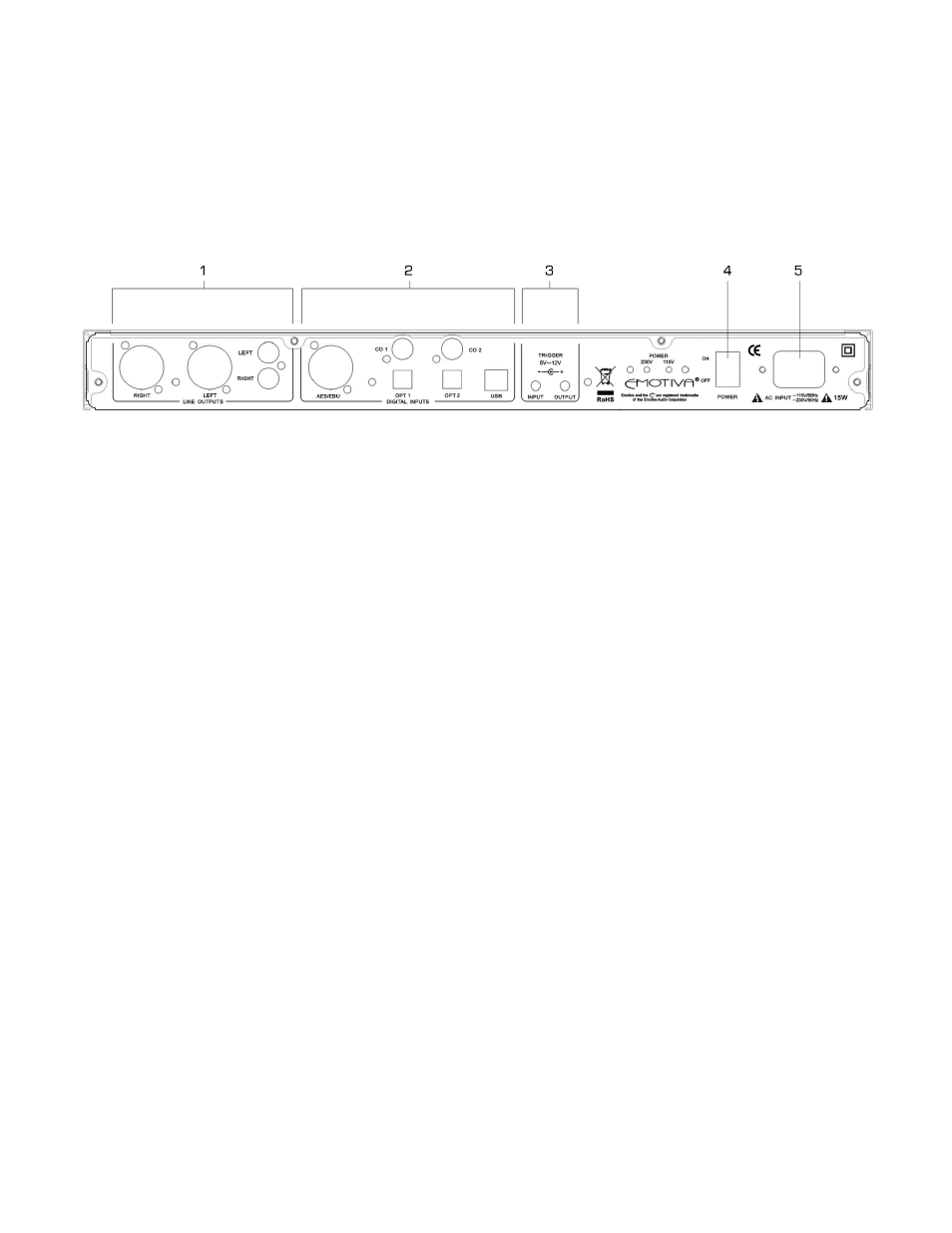
XDA-1 Rear Panel Layout
(for larger image, see page 22)
1. LINE AUDIO OUTPUTS Section (from left to right)
• XLR RIGHT OUTPUT
• XLR LEFT OUTPUT
• RCA LEFT OUTPUT
• RCA RIGHT OUTPUT
2. DIGITAL AUDIO INPUTS Section (from left to right)
• AES/EBU
• CO.1
• CO.2
• OPT.1
• OPT.2
• USB.
3. TRIGGER IN/OUT
3.1 TRIGGER INPUT
Allows a mono to mono 3.5mm cable to remotely trigger the XDA-1 on and off. Current is limited to 500ma
3.2 TRIGGER OUTPUT
Allows a mono to mono 3.5mm cable to remotely trigger another device on and off, along with the XDA-1.
Current is limited to 500mA, which is sufficient to trigger two devices. For triggering more devices, you may
want to use a separate triggering device, like the Emotiva ET-3.
4. Main Power Switch
This rocker switch provides the master power for the XDA-1. After it is in the ON position, the XDA-1 can be
turned on manually from the front panel switch, remote control, or automatically with the trigger input via a
3.5mm input jack.
5. Power Receptacle
Uses standard IEC power cord.