Instruction manual, Caution – Emerson Process Management FISHER 657 User Manual
Page 4
Instruction Manual
D100306X012
657 Actuator (30-70 and 87)
December 2010
4
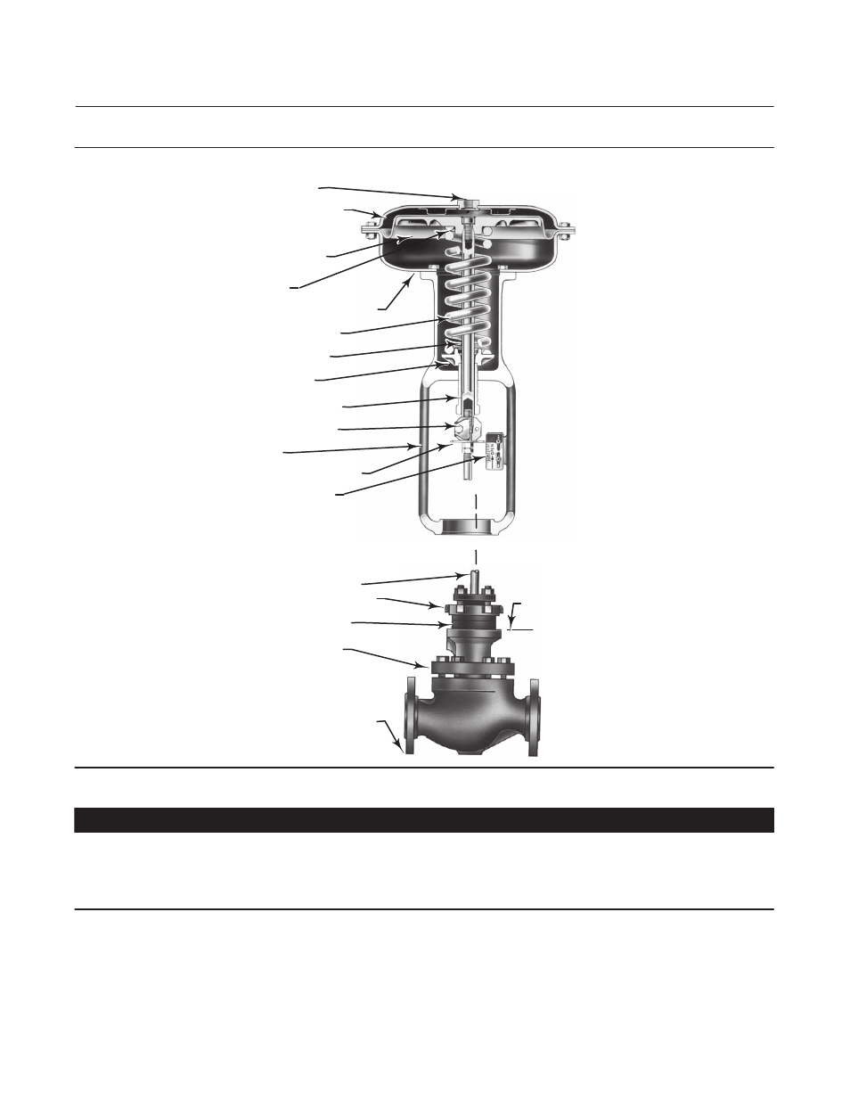
Figure 3. Actuator Mounting Components for Size 30 through 70 Actuators
VALVE STEM
YOKE LOCK NUT
YOKE BOSS DIAMETER
BONNET
TYPICAL VALVE
(REFER TO VALVE MANUAL)
W6199-1
MATCH LINE
FOR ACTUATOR
NPT INTERNAL CONNECTION
DIAPHRAGM CASING
DIAPHRAGM AND STEM
SHOWN IN UP POSITION
DIAPHRAGM PLATE
ACTUATOR SPRING
ACTUATOR STEM
SPRING SEAT
SPRING ADJUSTOR
STEM CONNECTOR
YOKE
TRAVEL INDICATOR DISK
INDICATOR SCALE
W0363-1
LOWER DIAPHRAGM CASING
CAUTION
To avoid parts damage, do not use an operating pressure that exceeds the Maximum Diaphragm Casing Pressure (table 1)
or produces a force on the actuator stem greater than the Maximum Allowable Output Thrust (table 1) or the maximum
allowable valve stem load. (Contact your Emerson Process Management sales office with questions concerning maximum
allowable valve stem load.)
D Valve/Actuator Assembly: If the actuator and valve are shipped together as a control valve assembly, it has been
adjusted at the factory, and may be installed in the pipeline. After installing the valve in the pipeline, refer to the
Loading Connection procedures.