Empire Comfort Systems DV-55T-1 User Manual
Page 10
13118-7-0408
Page 10
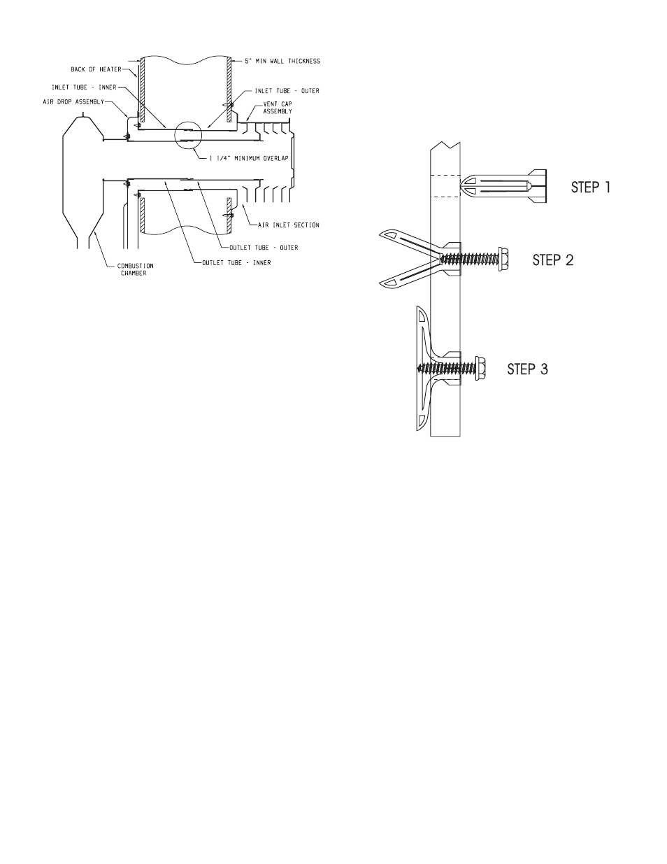
Using Plastic Expansion Anchors
1. After locating mounting holes, drill two (2) 5/16" diameter
holes into the wall.
2. Insert two (2) plastic expansion anchors provided into the
holes.
3. Tighten two (2) 10 x 1" screws provided into the plastic
expansion anchors. (See Figure 9)
Figure 9
Attention! The screw holes on the outer casing bottom are off-set
above the floor approximately 3/8". Do not over-tighten screws
and distort the off-set on the outer casing bottom. Distortion of
the outer casing bottom will not allow the lower front panel to be
attached to the furnace.
Installing Vent Assembly
Attention: DO NOT attempt to cut vent tubes. When you order
appropriate vent kit for measured wall depth the vent tubes will
fit together.
1. Place provided caulking beneath the collar of the outside
mounting plate. Use additional caulking to correct uneven wall
surface, such as clapboard.
2. Insert six inch air tube on outside mounting plate INTO six inch
air tube attached to air drop. Place four inch flue tube on vent
cap OVER four inch flue tube attached to combustion chamber.
Position the outside mounting plate so that six inch air tube
has a slight downward slope to the outside. The downward
slope is necessary to prevent the entry of rainwater. Attach
outside mounting plate to exterior wall with four (4) 10 x 1 1/2"
screws.
3. Installation is completed.
Reassembly And Resealing Vent-Air Intake System
When vent-air intake system is removed for servicing the furnace,
the following steps will assure proper reassembly and resealing of
the vent-air intake assembly.
Figure 8
Locating Electric Supply
A 7/8" diameter knockout is provided at the bottom of the left
and right side panels. A three-prong (grounding) plug assembly is
located within the control compartment (bottom) of the furnace.
Please remove 7/8" knockout from appropriate side panel when
routing plug assembly to an electrical outlet.
Installation of Three-prong (Grounding) Plug Assembly
1. Disconnect nylon cap on 3' plug assembly from nylon plug on
wiring harness. Remove 3' plug assembly from control compart-
ment (bottom) of the furnace.
2. Remove 7/8" knockout from appropriate side panel.
3. Insert nylon cap on 3' plug assembly into the 7/8" hole in the
side panel.
4. Connect nylon cap on 3' plug assembly to nylon plug on the
wiring harness.
5. Place 7/8" strain relief bushing around the cord of the 3' plug
assembly. Insert 7/8" strain relief bushing into the 7/8" hole in
the side panel.
Attention! The 7/8" strain relief bushing is located within the same
envelope as the Installation Instructions and Owner's Manual.
Attaching Furnace to Wall
Place collar on four inch flue tube against combustion chamber back.
Align clearance holes on collar with screw holes in combustion
chamber back. Attach four inch flue tube to combustion chamber
back with four (4) 10 x 1/2" screws.
Place collar on six inch air tube against air drop. Align clearance
holes on collar with screw holes in air drop. Attach six inch air tube
to air drop with eight (8) 10 x 1/2" screws.
Refer to Figure 5 for the location of the 7 1/2" diameter wall open-
ing for the furnace. After the wall opening has been located and
cut, position flue outlet on furnace in center of wall opening. Insert
tubes through wall opening. When attaching furnace to the wall
remove that portion of baseboard and molding on the wall which is
behind the furnace. Attach furnace to wall, at the outer casing top,
with two (2) plastic expansion anchors provided and to floor, at the
outer casing bottom, with two (2) 10 x 1 1/2" screws provided.