Magnum Energy Mini Magnum Panel (MMP Series) User Manual
Page 58
Page 49
©
2013 Magnum Energy, Inc.
Appendix A - Optional Equipment and Accessories
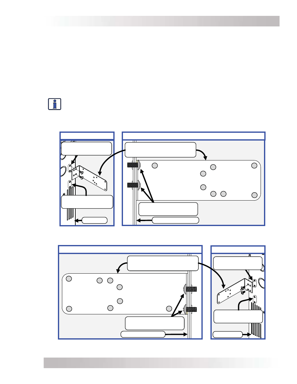
Refer to Figure A1-2 to locate the holes you will use to attach the charge controller to the bracket.
Before mounting the bracket, use the provided T20 Torx drive, thread forming screws to pre-thread
your selected mounting holes. It is easier to thread the holes now rather than doing it after the
bracket and controller have been installed.
After pre-threading your particular bracket hole(s), locate the enclosure mounting holes you will
use to attach the bracket to the enclosure. Before you mount the charge controller to the attached
bracket, remove the appropriate knockout from the side of the controller and an adjacent knockout
on the side of the enclosure. This allows you to use a one inch close nipple with two locknuts to
secure the charge controller to the enclosure (in addition to the bracket), and provides a path to
run the necessary wiring between the two units. Mount the controller to the attached bracket using
the supplied hardware. Insert the close nipple through the knockouts and secure with the locknuts.
Info: It may take three locknuts on the close nipple to anchor the controller to the
enclosure. An additional locknut may be required between the enclosure and the
controller to act as a spacer. Also, a standard one inch plastic bushing should be used
on the nipple ends to protect the wire insulation as it enters/exits the nipple.
Figure A1-2, Holes Used to Mount Bracket on MMP Enclosure
Left Front View
Charge Control Bracket
(left side)
Bracket to enclosure
Torx screws
Controller Mounting
Holes on Bracket
Left Side View
MMP Enclosure
MMP
Lower Mounting
Holes (left side)
Upper Mounting
Holes (left side)
Right Front View
Charge Control Bracket
(right side)
Controller Mounting
Holes on Bracket
MMP Enclosure
Bracket to enclosure
Torx screws
MMP
Lower Mounting
Holes (right side)
Upper Mounting
Holes (right side)
A
B
C
D
F
E
G
A
B
C
D
F
G
Right Side View