Magnum Energy DC Breakers (BR-DC) User Manual
Page 2
High Capacity DC Breakers Instruction Sheet
2
© 2010 Magnum Energy, Inc.
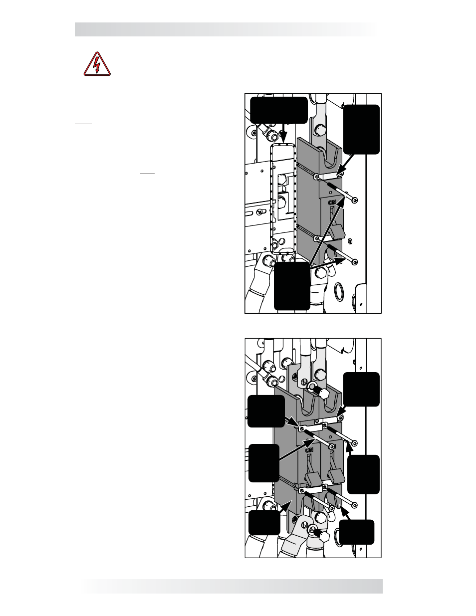
Installation Steps:
1. Remove the breaker front panel cover
only after all power has been removed
from the Magnum Panel system.
2. Using a T25 screwdriver, remove only
the two #10-32 x 3.5” Torx screws that
attach the existing DC breaker to the
mounting plate and are adjacent to the
location that you will add your new DC
breaker (see Figure 2).
3. Place the new breaker against the
mounting plate adjacent to the existing
breaker; with one side of the new DC
breaker placed under the side where the
two mounting straps are loose.
4. While holding the new breaker in place,
attach two new mounting straps over the
new DC breaker. Ensure the holes on the
two new mounting straps – that are over
the existing DC breaker – line up with the
holes on the two existing mounting straps
(see Figure 3).
5. Insert the two Torx screws that were
removed in Step 2 into the aligned holes
of the new and existing mounting straps,
and tighten to secure the existing DC
breaker.
6. Insert two new #10-32 x 3.5” Torx
screws into the other side of the new
mounting straps and screw down enough
to hold the new DC breaker in place. Do
not fully tighten the screws, that will be
done in Step 7 after being aligned.
Note: The holes in the mounting plate - for
the Torx screws that hold the new breaker
- are NOT prethreaded. Use a power-driver
to screw these self-threading Torx screws
(T25 head) into the mounting plate.
7. Check the DC breaker alignment by
placing the front panel cover over the
DC breakers. If the fi t and alignment are
correct, tighten all Torx screws to secure
the new DC breaker. Note: Be careful not
to over-tighten and bend down the tabs
on the mounting straps.
The DC breaker is now installed. Connect
the inverter and battery cables with the
3/8-16 bolts/washers provided.
Le a v e
e x is ting
m ounting
s tra ps
(x 2)
in pla c e
M ounting P la te
(loc a tion for
ne w bre a k e r)
R e m ov e
s c re ws
a dja c e nt
to ne w
bre a k e r
loc a tion
Figure 2, Removing Screws
Figure 3, Install New Breaker
N e w
m ounting
s tra ps
(x 2)
E x is ting
m ounting
s tra ps
(x 2)
E x is ting
torx
s c re ws
(x 2 )
N e w
torx
s c re ws
(x 2 )
E x is ting
D C
bre a k e r
N e w
D C
bre a k e r
WARNING: During normal operation, the terminals, busbars, and
electrical components inside the MP enclosure may be energized
- DO NOT TOUCH. Disconnect all power sources before removing
the cover. Failure to take action could result in physical harm.