Interference considerations, Helpful application notes from linx, Power supply requirements – Linx Technologies EVM-915-DTS User Manual
Page 8
–
–
–
–
11
10
Helpful Application Notes from Linx
It is not the intention of this manual to address in depth many of the issues
that should be considered to ensure that the modules function correctly
and deliver the maximum possible performance. As you proceed with your
design, you may wish to obtain one or more of the following application
notes which address in depth key areas of RF design and application of
Linx products. These application notes are available online at
www.linxtechnologies.com or by contacting Linx.
Power Supply Requirements
The transceiver incorporates a precision
low-dropout regulator which allows operation
over a wide input voltage range. Despite this
regulator, it is still important to provide a supply
that is free of noise. Power supply noise can
significantly affect the module’s performance, so
providing a clean power supply for the module
should be a high priority during design.
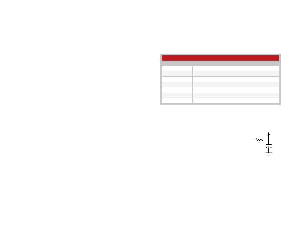
A 10
Ω resistor in series with the supply followed by a 10μF tantalum
capacitor from V
cc
to ground helps in cases where the quality of supply
power is poor (Figure 10). This filter should be placed close to the module’s
supply lines. These values may need to be adjusted depending on the
noise present on the supply line.
Interference Considerations
The RF spectrum is crowded and the potential for conflict with unwanted
sources of RF is very real. While all RF products are at risk from
interference, its effects can be minimized by better understanding its
characteristics.
Interference may come from internal or external sources. The first step
is to eliminate interference from noise sources on the board. This means
paying careful attention to layout, grounding, filtering and bypassing in
order to eliminate all radiated and conducted interference paths. For
many products, this is straightforward; however, products containing
components such as switching power supplies, motors, crystals and other
potential sources of noise must be approached with care. Comparing your
own design with a Linx evaluation board can help to determine if and at
what level design-specific interference is present.
External interference can manifest itself in a variety of ways. Low-level
interference produces noise and hashing on the output and reduces the
link’s overall range.
High-level interference is caused by nearby products sharing the same
frequency or from near-band high-power devices. It can even come from
your own products if more than one transmitter is active in the same area.
It is important to remember that only one transmitter at a time can occupy
a frequency, regardless of the coding of the transmitted signal. This type of
interference is less common than those mentioned previously, but in severe
cases it can prevent all useful function of the affected device.
Although technically not interference, multipath is also a factor to be
understood. Multipath is a term used to refer to the signal cancellation
effects that occur when RF waves arrive at the receiver in different phase
relationships. This effect is a particularly significant factor in interior
environments where objects provide many different signal reflection paths.
Multipath cancellation results in lowered signal levels at the receiver and
shorter useful distances for the link.
Helpful Application Note Titles
Note Number
Note Title
AN-00100
RF 101: Information for the RF Challenged
AN-00126
Considerations for Operation Within the 902–928MHz Band
AN-00130
Modulation Techniques for Low-Cost RF Data Links
AN-00140
The FCC Road: Part 15 from Concept to Approval
AN-00160
Considerations for Sending Data Over a Wireless Link
AN-00500
Antennas: Design, Application, Performance
AN-00501
Understanding Antenna Specifications and Operation
Figure 9: Helpful Application Notes
+
10
Ω
10
µF
Vcc IN
Vcc TO
MODULE
Figure 10: Supply Filter