Pin assignments, Pin descriptions – Linx Technologies HUM-xxx-RC User Manual
Page 11
– –
– –
16
17
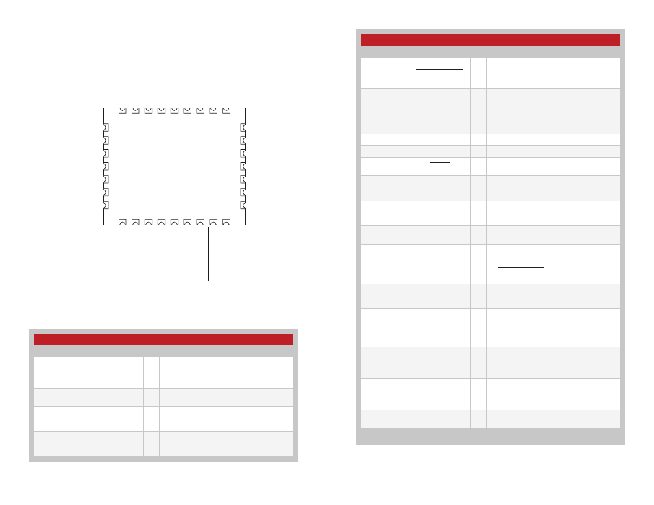
Pin Assignments
30
31
32
1
2
3
4
20
19
18
17
16
15
14
5
6
7
8
9 10 11 12 13
29 28 27 26 25 24 23 22 21
ANT
GND
GND
GND
GND
GND
GND
ACK_OUT
MODE_IND
LVL_ADJ
S7
S4
S5
S6
S2
S3
S1
S0
C1
C0
GND
LATCH_EN
POWER_DOWN
ACK_EN
PAIR
CMD_DATA_IN
CMD_DATA_OUT
LNA_EN
PA_EN
GND
VCC
RESET
Figure 26: HumRC
TM
Series Transceiver Pin Assignments (Top View)
Pin Descriptions
Pin Number
Name
I/O Description
1, 2, 3, 4, 5,
6, 7, 8
S0–S7
1
I/O
Status Lines. Each line can be configured
as either an input to register button or
contact closures or as an output to control
application circuitry.
9, 14, 15, 16,
17, 18, 20, 25
GND
—
Ground
10
C0
I
This line sets the input/output direction for
status lines S0-S3. When low, the lines are
outputs; when high they are inputs.
11
C1
I
This line sets the input/output direction for
status lines S4-S7. When low, the lines are
outputs; when high they are inputs.
Pin Descriptions
Pin Number
Name
I/O Description
12
POWER_DOWN
I
Power Down. Pulling this line low places the
module into a low-power state. The module
is not functional in this state. Pull high for
normal operation. Do not leave floating.
13
LATCH_EN
I
If this line is high, then the status line
outputs are latched (a received command
to activate a status line toggles the output
state). If this line is low, then the output lines
are momentary (active for as long as a valid
signal is received).
19
ANTENNA
—
50-ohm RF Antenna Port
21
VCC
—
Supply Voltage
22
RESET
I
This line resets the module when pulled low.
It should be pulled high for normal operation.
23
LNA_EN
0
Low Noise Amplifier Enable. This line is
driven high when receiving. It is intended to
activate an optional external LNA.
24
PA_EN
O
Power Amplifier Enable. This line is driven
high when transmitting. It is intended to
activate an optional external power amplifier.
26
CMD_DATA_OUT
O
Command Data Out. Output line for the
serial interface commands
27
CMD_DATA_IN
I
Command Data In. Input line for the serial
interface commands. If serial control is not
used, this line should be tied to ground
or POWER_DOWN to minimize current
consumption.
28
ACK_EN
I
Pull this line high to enable the module to
send an acknowledgement message after a
valid control message has been received.
29
PAIR
1
I
A high on this line initiates the Pair process,
which causes two units to accept each
other’s transmissions. It is also used with
a special sequence to reset the module to
factory default configuration.
30
MODE_IND
O
This line indicates module activity. It can
source enough current to drive a small
LED, causing it to flash. The duration of the
flashes indicates the module’s current state.
31
ACK_OUT
O
This line goes high when the module
receives an acknowledgement message
from another module after sending a control
message.
32
LVL_ADJ
I
Level Adjust. The voltage on this line sets
the transmitter output power level.
1. These lines have an internal 20k
Ω pull-down resistor
Figure 27: HumRC
TM
Series Transceiver Pin Descriptions
Pin Descriptions