Typical applications, Initialization complete message, Figure 58 shows a typical cir cuit using the humdt – Linx Technologies HUM-xxx-DT User Manual
Page 29: They should be connected directly to v
– –
– –
52
53
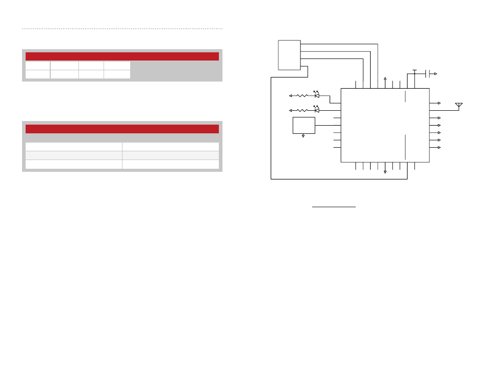
Typical Applications
Figure 58 shows a typical circuit using the HumDT
TM
Series transceiver.
An external microcontroller provides data and configuration commands. It
also controls the POWER_DOWN line to place the module into a low power
state.
A sensor is connected to GPIO_1. This sensor outputs an analog voltage
that is proportional to the parameter being measured. GPIO_1 is set as an
analog input and the microcontroller can query the voltage state of the line.
The VCCD lines are not connected in this example. These lines are unused
inputs with 20k resistors to V
CC
. They should be connected directly to V
CC
if noise on the board or in the environment could cause voltage drops on
the lines that fall below the V
IH
specification. This is not likely to be an issue
with most battery-powered devices, but could be a problem with designs
containing switching power supplies or used near motors or other sources
of high-level EMI. This should be tested with all designs.
µ
RXD
TXD
GND
VCC
GND
GND
GND
GND
GND
GND
GND
GND
GPIO
GND
17
VCC
21
GND
18
RESET
22
LNA_EN
23
PA_EN
24
CMD_DATA_OUT
26
CMD_DATA_IN
27
CTS
28
VCCD
29
GPIO_2
2
GND
25
GPIO_1
1
MODE_IND
30
ACTIVE
31
GPIO_0
32
GPIO_3
3
GPIO_4
4
ANT
19
GND
20
GPIO_
5
5
GPIO_
6
6
GPIO_
7
7
VCCD
8
VCCD
10
VCCD
11
POWER_DOW
N
12
VCCD
13
GND
9
GND
16
GND
15
GND
14
GND
GND
GPIO
GPIO
Sensor
GND
Figure 58: HumDT
TM
Series Transceiver Basic Application Circuit
Initialization Complete Message - Response Code = 7A
Once the module has completed its power-up initialization routines and
joined the network, it outputs the message shown in Figure 56.
The DType parameter is the device type that the module has assumed
during initialization. These codes are shown in Figure 57.
The microcontroller can confirm that this is the correct device type for the
application and make changes as necessary.
Device Type Codes
Device Type
Device Type Code (hex)
Access Point (AP)
31
Range Extender (RE)
32
End Device (ED)
33
Figure 57: Baud Rate Codes
Initialization Complete Message
Start
Response
Param 1
End
3C
7A
DType
3E
Figure 56: Initialization Complete Message