Front components, Chapter 2, System components – Lanner LEC-7950 User Manual
Page 8
7
System Components
Chapter 2
Embedded and Industrial Computing
Component
Description
Pin Definition
Reference
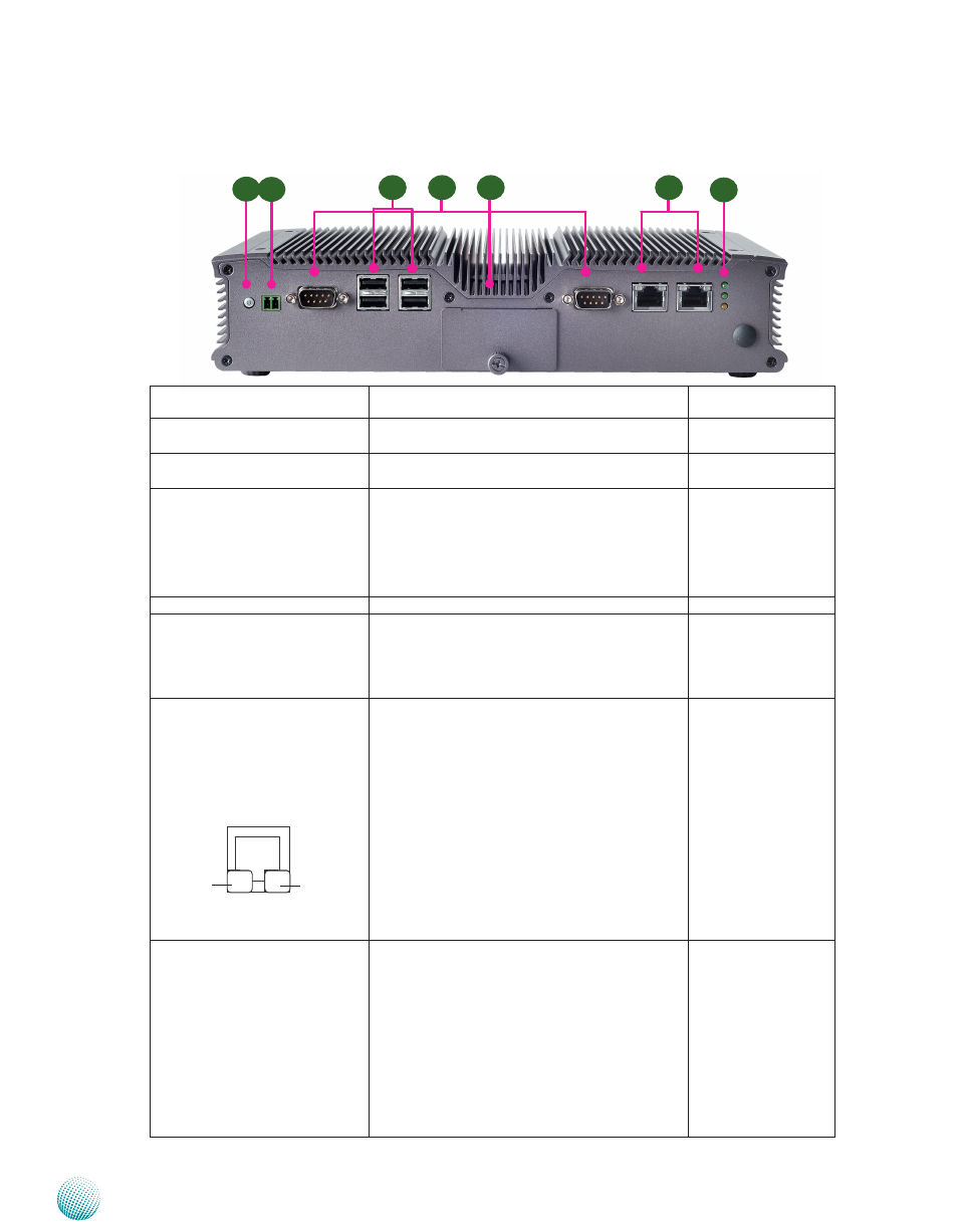
F1 Power Button with dual LED
ATX Power-on button with LEDs: Standby mode in
Red; Power-on mode in Green
PBT1 on page 15
F2 Power-on Switch
A power-on switch through the terminal block for
distant power-on/off control
J1 on page 16
F3 Serial Port COM1 and COM2
Serial ports through the DB-9 connector; Both
COM1 and COM2 support RS-232/422/485 with
jumper selection (and BIOS menu) among RS-
232/422/485. They also support hardware auto
flow control. Besides these two external ports,
two RS-232 ports are provided via pin headers.
CN3/CN4 on page 12
F4 Dual USB 2.0 Ports
An USB type A connector.
USB1 on page 17
F5 CF/SIM Card Reader
External SIM Card Reader for 3G wireless Internet
service. The system supports 3G Internet service
with one Mini-PCIe (MPCIE1) one SIM card reader
(SIM1). The CF card can be accessed from the
front panel too.
SIM1 on page 14
F6 Two 10/100/1000Mbps LAN
ports
Two RJ-45 (network) jacks with LED indicators as
described below. Both LAN ports are provided by
Intel 82583V. The 82583V supports PXE remote
boot
LINK/ACT (Yellow)
On/Flashing: The port is linking and active in
•
data transmission.
Off: The port is not linking.
•
SPEED (Green/Amber)
Amber: The connection speed is 1000Mbps.
•
Green: The connection speed is 100Mbps
•
Off: The connection speed is 10Mbps.
•
LAN1/LAN2 on page
15
F7 Power LED (Green)
Status (Green)
HDD (Yellow)
HDD
Blinking: data access activities
•
Off: no data access activities
•
Status
A programmable dual green/orange LED which
can be used for indicating system status.
Power
On: The computer is on.
•
Off: The computer is off .
•
Front Components
sPEEd
LINK/ACT
F2
F6
F5
F4
F1
F3
F7