Jumper settings, Chapter 3, Board layout – Lanner LEC-7950 User Manual
Page 13
12
Board Layout
Chapter 3
Embedded and Industrial Computing
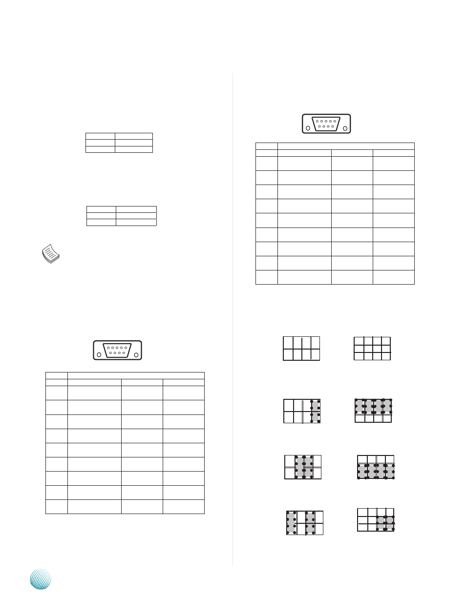
COM2 RS-232/422/485 Serial Port(CN4): It is a RS-
232/422/485 port through the D-SUB9 connector.
J10, SC2T1: Select COM1 Protocol Setting
RS-232
RS-422
RS-485
Jumper Settings
Audio Line-in RCA Connector Right and Left (J4, J5)
Audio Line-out RCA Connector Right and Left (J2, J3)
Note: The driver for the VGA and Audio ports
should be installed with the following order:
Chipset INF->Graphic->Audio
COM1 RS-232/422/485 Serial Port (CN3): It is a RS-
232/422/485 port through the D-SUB9 connector.
Pin No.
Function
1
Front_out
2
GNd
Pin No.
Function
1
Front_out
2
GNd
SC2T1
J10
1
2
6 7 8 9
1 2 3 4 5
Pin No.
Pin Name
Rs-232
Rs-422
Rs-485
1
data Carrier detect
(dCdA # )
TXd-
dATA-
2
Receive data
(RXdA )
TXd+
dATA+
3
Transmit data
(TXdA )
RXd+
4
data Terminal Ready
(dTRA # )
RXd-
5
Ground
(GNd )
6
data set Ready
(dsRA # )
7
Request To send
(RTsA # )
8
Clear To send
(CTsA # )
9
Ring Indicator
(RIA # )
7
8
4
8
12
1
5
9