Lanner LEC-7020 User Manual
Page 15
LEC-7020 Fanless Embedded System User
’
s Manual
15
16. CN2: DVI-D output (only for LEC-7020D)
Pin No.
Description
Pin No.
Description
Pin No.
Description
1
TMDS Data 2-
9
TMDS Data 1-
17
TMDS Data 0-
2
TMDS Data 2+
10
TMDS Data 1+
18
TMDS Data 0+
3
TMDS Data 2/4 shield
11
TMDS Data 1/3 shield
19
TMDS Data 0/5 shield
4
TMDS Data 4-
12
TMDS Data 3-
20
TMDS Data 5-
5
TMDS Data 4+
13
TMDS Data 3+
21
TMDS Data 5+
6
DDC CLOCK
14
5V
22
TMDS CLK shield
7
DDC DATA
15
GND
23
TMDS CLK+
8
Analog vertical sync
16
HOT PLUG DET
24
TMDS CLK-
17. VGA1: DB15 for VGA output
Pin No. Description Pin No. Description Pin No. Description
1
CRT-R
6
GND
11
NC
2
CRT-G
7
GND
12
V_SDAT
3
CRT-B
8
GND
13
HSYNC
4
NC
9
VCC
14
VSYNC
5
GND
10
GND
15
V_SCLK
18. DC1: DC-Jack with lock for +12Vdc Input
19. LED2: LED in Yellow color for storage access and LED in Green color for Power-on
20. LED3: LED in Yellow color for storage access and LED in Green color for Power-on
21. CN1: DDR2 SO-DIMM socket for DDR2 SO-DIMM system memory module up to 2GB
capacity
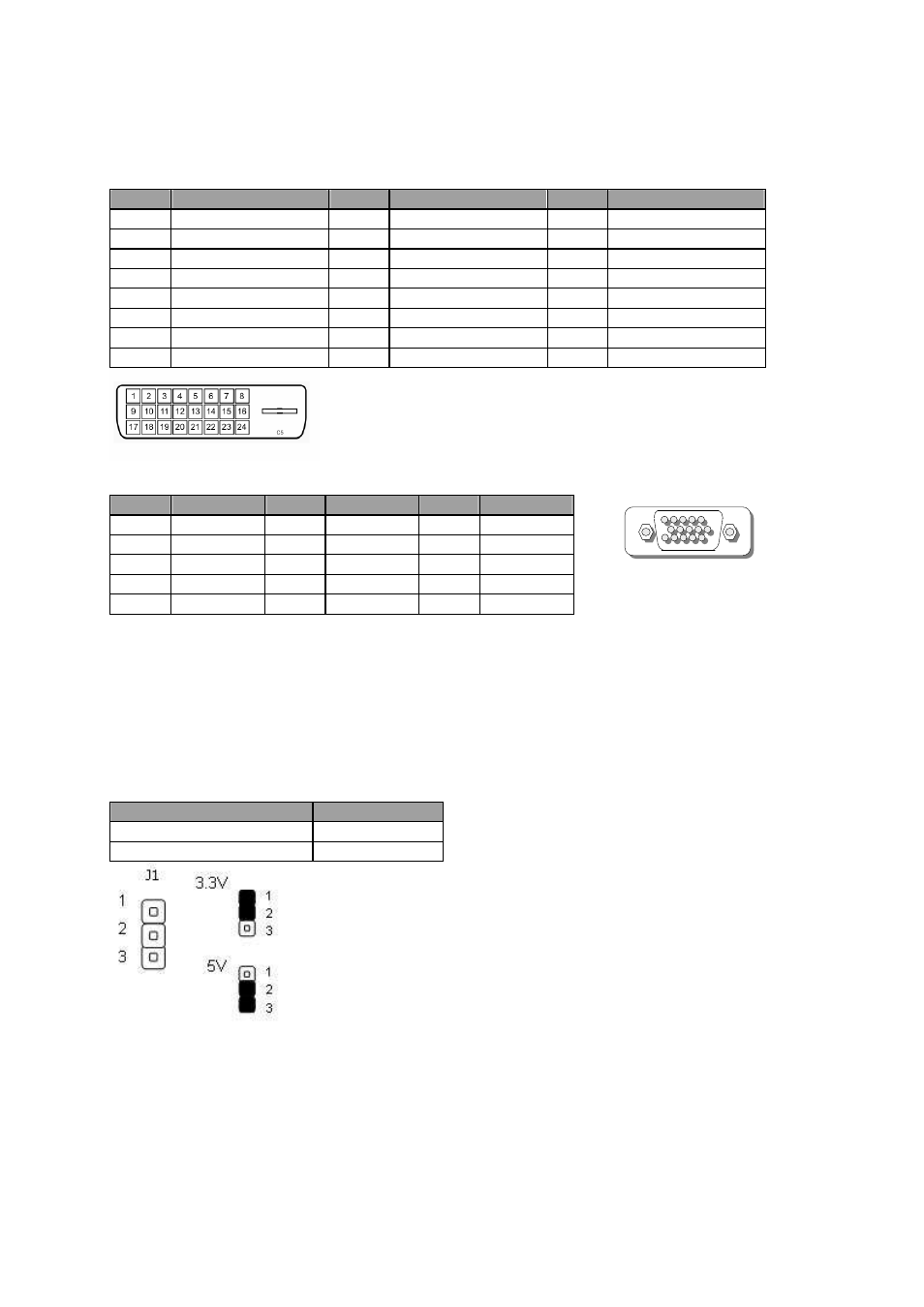
22. J1: Clear CMOS setting
Description
CMOS
3.3V(Default)
1-2
5V
2-3
(VGA)
5
1