2 jumper settings and i/o connectors, 1 connector pin assignments, Item no location description 1 – Lanner LEC-7020 User Manual
Page 12
LEC-7020 Fanless Embedded System User
’
s Manual
12
2.2 Jumper Settings and I/O Connectors
The jumper settings and I/O connectors of the LEB-7020 board
are specific to the LEC-7020.
Changing these settings may result in malfunctions or damages to your system.
Jumper Settings and I/O Connector Summary for LEB-7020:
Item No
Location
Description
1
COM2
DIO for 4x DI and 4x DO
2
USB1,2
2x Dual-type A USB connectors
3
LANB1,2
2x RJ45 for Ethernet ports
4
J6
Microphone input Phone-Jack Connector
5
J7
Line-out Phone-Jack Connector
6
SW2
ATX Power-on switch with LED
7
CONN3
Power on connector
8
CN3
Type I/II CompactFlash socket
9
CON3
SIM card socket (only for 3G mini-card installed)
10
MPCIE1
Mini-PCIexpress socket
11
LED4
3G status (only for 3G mini-card installed)
12
CON2
+5V/+12V DC-out
13
J3
SATA
14
CONN2
Reset Connector
15
COM1
RS232
16
CN2
DVI-D output (only for LEC-7020D)
17
VGA1
DB15 for VGA output
18
DC1
+12DC input
19
LED2
Yellow: storage access; Green: power on
20
LED3
Yellow: storage access; Green: power on
21
CN1
DDR2 SO-DIMM socket
22
J1
Clear CMOS
2.2.1 Connector Pin Assignments
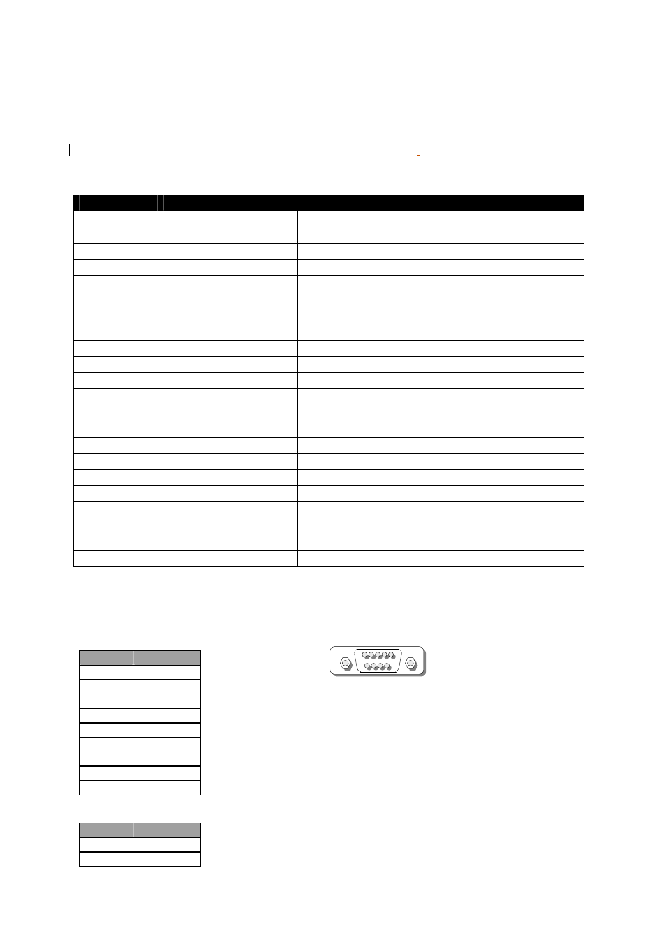
1. COM2: DIO ( D-SUB9) Connector
PIN NO.
Description
1
GPIO1
2
GPIO2
3
GPIO3
4
GPIO4
5
GROUND
6
GPIOA
7
GPIOB
8
GPIOC
9
GPIOD
2. USB1,2:
2x Dual-type A USB connectors
PIN NO.
Description
1
5V_USB1
2
-USB0
COM2
1
5
9
6