Installing the hard disk, Installing the compactflash card, Installing the 3g sim card – Lanner LEC-2250 User Manual
Page 20: Installing the wireless 3g module, Installing the wi-fi module, Chapter 4, Hardware setup
19
Hardware Setup
Chapter 4
Embedded and Industrial Computing
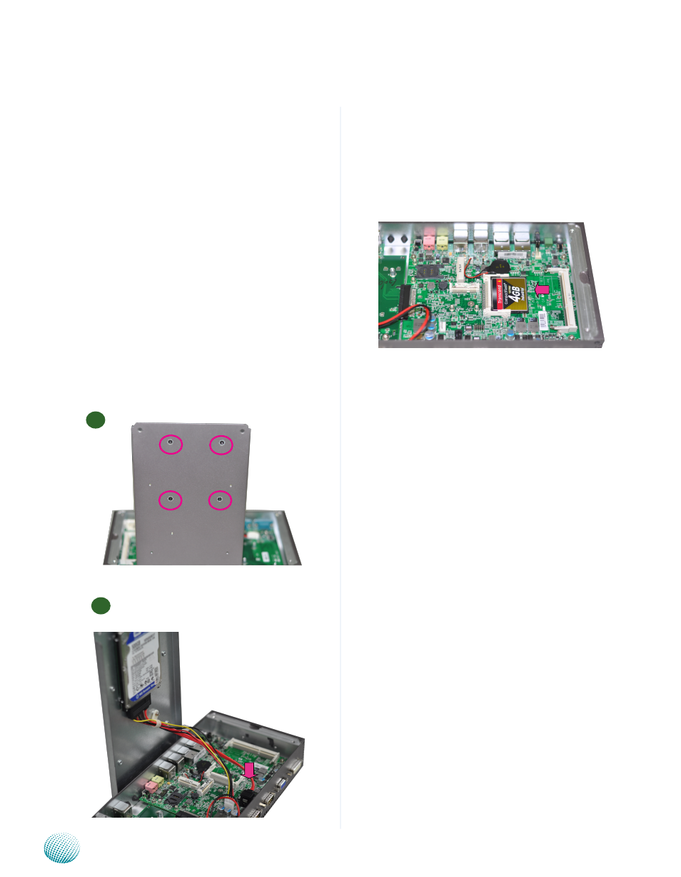
Installing the CompactFlash Card
LEC-2250 provides one CompactFlash slot. Follow the
procedures bellow for installing a CompactFlash card.
Align CompactFlash card and the card slot with the
1.
arrow pointing toward the connector.
Push the card to insert into the connector.
2.
Note:
The motherboards can support up to 4 GB
1.
memory capacity in maximum.
The CF has to be installed first (if it is needed)
2.
before you install the RAM due to space
contention.
Installing the 3G SIM Card
Unlock the SIM card reader by sliding it outward and
1.
flip it up diagonally.
Align the cut-corner of the SIM card with the SIM card
2.
reader. Make sure that the ICs will be in contact with
the bottom of the reader.
Insert the
3.
SIM card into the reader diagonally. Close
and lock the reader. You should feel a click when the
SIM card is locked securely in the reader.
Installing the Wireless 3G Module
Align the wireless module’s cutout with the Mini-PCIe
1.
slot notch.
Insert the wireless module into the connector
2.
diagonally.
Fasten the wireless module to the board with the
3.
screws (Use the Mini-PCIe module screws contained
within the package).
Installing the Wi-Fi Module
Follow the same steps as the Wireless 3G Module
Installation.
1
2
Installing the Hard Disk
The system can accommodate one Serial-ATA disks. Follow
these steps to install a hard disk into the LEC-2250:
Unscrew the 4 rubber feet from the bottom cover of
1.
the LEC-2250 System.
Place hard disk on the top cover of the system and
2.
align the holes of the hard disk with the mounting
holes of the top cover.
Secure the hard disk with 4 mounting screws from the
3.
outside of cover.
Connect the Serial-ATA power and data cables to the
4.
hard disk’s connectors.
Plug the Serial-ATA cables (power and data) to the
5.
Serial-ATA Connectors on the main board.