Chapter 3, Motherboard information – Lanner VES-270 User Manual
Page 14
14
Motherboard Information
Chapter 3
Embedded and Industrial Computing
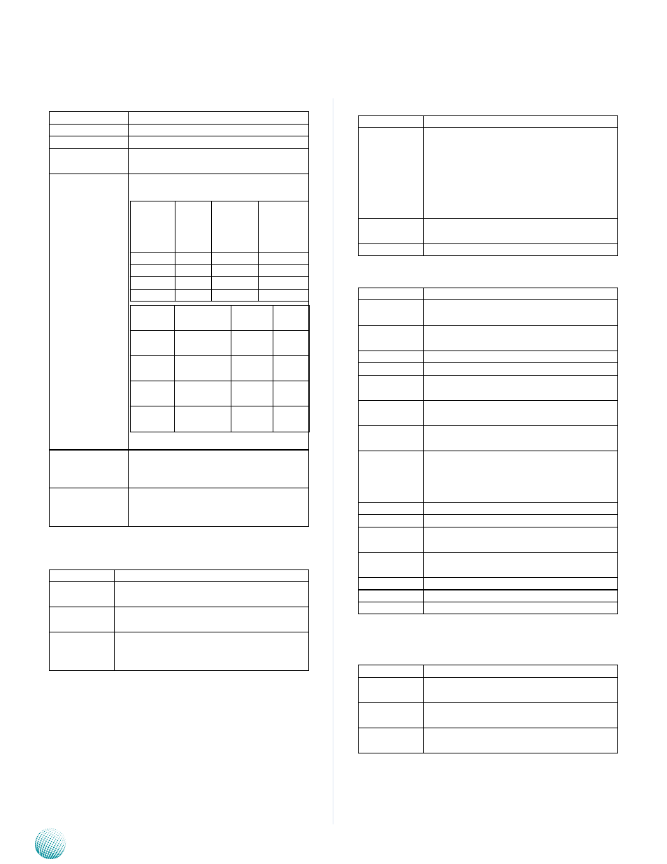
Miscellaneous Signals
•
Signal
Signal Description
I
2
C_CK
General purpose I
2
C port clock output
I
2
C_DAT
General purpose I
2
C port data I/O line
SPKR
Output for audio enunciator - the
"speaker" in PC-AT systems
BIOS_DIS0#
BIOS_DIS1#
Selection straps to determine the BIOS
boot device
BIOS_
DIS1#
BIOS_
DIS0#
Chipset
SPI CS1#
Destina-
tion
Chipset
SPI CS0#
Destina-
tion
1
1
Module Module
1
0
Module Module
0
1
Module Carrier
0
0
Carrier
Module
Carrier
SPI_CS#
SPI
Descriptor
BIOS
Entry
Ref
Line
High
Module
SPI0/
SPI1
0
High
Module
Carrier
FWH
1
SPI0
Carrier
SPI0/
SPI1
2
SPI1
Module
SPI0/
SPI1
3
KB_RST#
Input to module from (optional) exter-
nal keyboard controller that can force
a reset.
KB_A20GATE
Input to module from (optional) ex-
ternal keyboard controller that can be
used to control the CPU A20 gate line.
PCI Express Signals
•
Signal
Signal Description
PCIE_TX[0:4]
+/-
PCI Express Differential Transmit Pair 0-4
PCIE_RX[0:4]
+/-
PCI Express Differential Receive Pair 0-4
PCIE0_CK_
REF+/-
Reference clock output for PCI Express
lanes 0-7 and for PCI Express Graphics
lanes 0-15
Power Signals
•
Signal
Signal Description
VCC_5V_SBY Standby power input: +5.0V nominal. If
VCC5_SBY is used, all available VCC_5V_
SBY pins on the connectors must be
used. Only used for standby and suspend
functions. May be left unconnected if
these functions are not used in the system
design.
VCC_RTC
Real-time clock circuit-power input. Nomi-
nally +3.0V.
VIN
Primary power input: +9V~19V.
Power and System Management Signals
•
Signal
Signal Description
SUS_S3#
Indicates system is in suspend to RAM
state. Active low output.
SUS_S4#
Indicates system is in suspend to Disk
state. Active low output.
SUS_S5#
Indicates system is in Soft Off state.
BATLOW#
Indicates that external battery is low
PWRBTN#
Power button to bring system out of S5
(soft off), active on falling edge.
SMB_CK
System Management Bus bidirectional
clock line.
SMB_DTA
System Management Bus bidirectional
data line.
SMB_ALERT# System Management Bus Alert - input
can be used to generate an SMI# (System
Management Interrupt) or to wake the
system.
SUS_STAT#
Indicates imminent suspend operation.
PWR_OK
Power OK from main power supply
THRMTRIP# Active low output indicating that the CPU
has entered thermal shutdown.
THRM#
Input from off-module temp sensor indi-
cating and over-temp situation.
SYS_RESET# Reset button input. Active low input.
WAKE0#
PCI Express wake up signal.
WAKE1#
General purpose wake up signal.
SATA Signals
•
Signal
Signal Discription
SATA[0:3]_TX
+/-
Serial ATA Channel 0-3 transmit differen-
tial pair.
SATA[0:3]_RX
+/-
Serial ATA Channel 0-3 receive differential
pair.
ATA_ACT#
ATA (parallel and serial) activity indicator,
active low.