Chapter 3, Motherboard information – Lanner VES-220 User Manual
Page 14
11
Motherboard Information
Chapter 3
Embedded and Industrial Computing
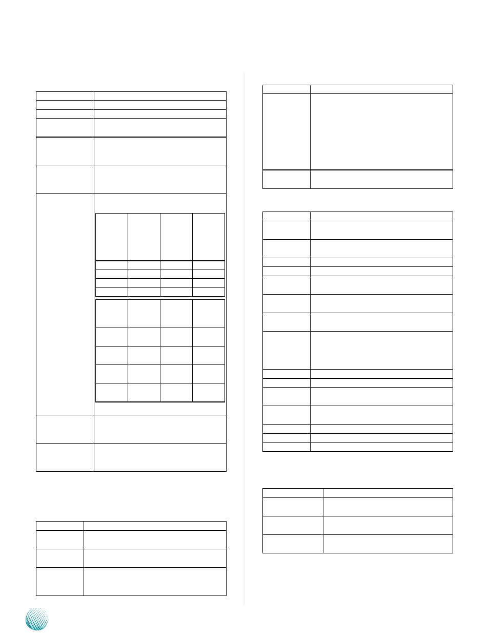
Miscellaneous Signals
•
Signal
Signal Description
I
2
C_CK
General purpose I
2
C port clock output
I
2
C_DAT
General purpose I
2
C port data I/O line
SPKR
Output for audio enunciator - the
"speaker" in PC-AT systems
KBD_RST#
Input to Module from (optional) exter-
nal keyboard controller that can force
a reset.
KBD_A20GATE Input to Module from (optional) ex-
ternal keyboard controller that can be
used to control the CPU A20 gate line.
BIOS_DIS0#
BIOS_DIS1#
Selection straps to determine the BIOS
boot device
BIOS_
DIS1#
BIOS_
DIS0#
Chip-
set SPI
CS1#
Destina-
tion
Chip-
set SPI
CS0#
Destina-
tion
1
1
Module Module
1
0
Module Module
0
1
Module Carrier
0
0
Carrier
Module
Carrier
SPI_CS#
SPI
Descrip-
tor
Bios
Entry
Ref
Line
High
Module SPI0/
SPI1
0
High
Module Carrier
FWH
1
SPI0
Carrier
SPI0/
SPI1
2
SPI1
Module SPI0/
SPI1
3
KB_RST#
Input to module from (optional) exter-
nal keyboard controller that can force
a reset.
KB_A20GATE
Input to module from (optional) ex-
ternal keyboard controller that can be
used to control the CPU A20 gate line.
PCI Express Signals
•
Signal
Signal Description
PCIE_TX[0:3]
+/-
PCI Express Differential Transmit Pair 0-3
PCIE_RX[0:3]
+/-
PCI Express Differential Receive Pair 0-3
PCIE0_CK_
REF+/-
Reference clock output for PCI Express
lanes 0-7 and for PCI Express Graphics
lanes 0-15
Power Signals
•
Signal
Signal Description
VCC_5V_SBY Standby power input: +5.0V nominal.
See Electrical Specifications for allowable
input range. If VCC5_SBY is used, all avail-
able VCC_5V_SBY pins on the connectors
must be used. Only used for standby and
suspend functions. May be left uncon-
nected if these functions are not used in
the system design.
VCC_RTC
Real-time clock circuit-power input. Nomi-
nally +3.0V.
Power and System Management Signals
•
Signal
Signal Description
SUS_S3#
Indicates system is in Suspend to RAM
state. Active low output.
SUS_S4#
Indicates system is in Suspend to Disk
state. Active low output.
SUS_S5#
Indicates system is in Soft Off state.
BATLOW#
Indicates that external battery is low
PWRBTN#
Power button to bring system out of S5
(soft off), active on rising edge.
SMB_CK
System Management Bus bidirectional
clock line.
SMB_DTA
System Management Bus bidirectional
data line.
SMB_ALERT# System Management Bus Alert - input
can be used to generate an SMI# (System
Management Interrupt) or to wake the
system.
SUS_STAT#
Indicates imminent suspend operation.
PWR_OK
Power OK from main power supply
THRMTRIP# Active low output indicating that the CPU
has entered thermal shutdown.
THRM#
Input from off-module temp sensor indi-
cating and over-temp situation.
SYS_RESET# Reset button input. Active low input.
WAKE0#
PCI Express wake up signal.
WAKE1#
General purpose wake up signal.
SATA Signals
•
Signal
Signal Discription
SATA[0:1]_TX +/- Serial ATA Channel 0-1 transmit dif-
ferential pair.
SATA[0:1]_RX +/- Serial ATA Channel 0-1 receive dif-
ferential pair.
ATA_ACT#
ATA (parallel and serial) activity indica-
tor, active low.