Chapter 3, Motherboard information, Jumper settings – Lanner MR-350 User Manual
Page 9
7
Motherboard Information
Chapter 3
Network Application Platforms
Jumper Settings
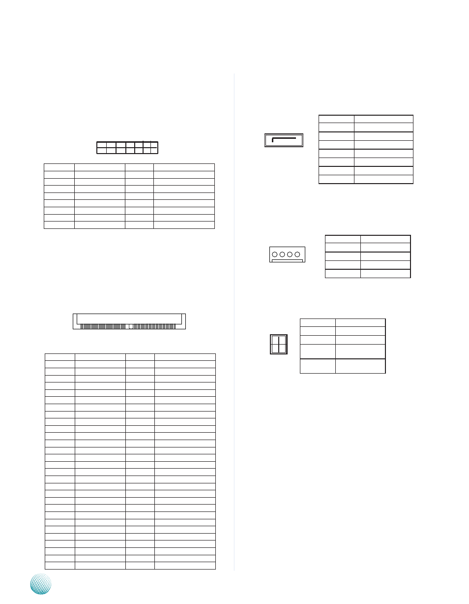
JTAG Port CPU (J1): A 2x8 (2.54mm) pin header is
a debug port provided as a means for testing the main
board and looking for possibility of field faults. It can also
be used for flash writing.
Mini-PCIe Connector (MPCIE1): The 52-pin Mini-
PCIe slot enables a Mini-PCIe expansion module to be
connected to the board. For example, a WiMAX/WiFi
module.
SATA Driver Connector (SATAB1): It is for connecting
a 2.5’’ SATA harddisk to be served as your system’s
storage. The system can support up to1 disk of 2.5” in
maximum.
Serial-ATA Power Connector (SATAPCN1): A 4-pin
(2.54mm) connector used for connectig the SATA power
cord.
Software Mode Pin Header (J12)
PIN NO.
FUNCTION
PIN NO.
FUNCTION
1
2
3.3V
3
4
GND
5
6
1.5V
7
8
9
GND
10
11
CLK_PCIE_N
12
13
CLK_PCIE_P
14
15
GND
16
17
18
GND
19
20
21
GND
22
23
PCIE_RX_N
24
25
PCIE_RX_P
26
GND
27
GND
28
1.5V
29
GND
30
31
PCIE_TX_N
32
33
PCIE_TX_P
34
GND
35
GND
36
37
38
39
40
GND
41
42
43
44
45
46
47
48
1.5V
49
50
GND
51
52
3.3V
53
GND
54
GND
55
GND
56
GND
57
GND
58
GND
20 18 16 14 12 10 8 6 4 2
19 17 15 13 11 9 7 5 3 1
PIN NO.
FUNCTION
PIN NO.
FUNCTION
1
CPU_TDO
2
Pull high 10k to3.3V
3
CPU_TDI
4
Pull high 10k to3.3V
5
COP_RUNSTOP
6
COPVSENSE
7
CPU_TCLK
8
CKSTP_IN_N
9
CPU_TMS
10
NA
11
CPU_SRST_N
12
GND
13
CPU_HRST_N
14
NA
15
CKSTP_OUT_N
16
GND
MPCIE2
Pin No.
Description
1
GND
2
TX_P
3
TX_N
4
GND
5
RX_N
6
RX_P
7
GND
Pin No.
Description
1
NA
2
GND
3
GND
4
5V
Pin No.
Description
00
Test Mode
01
Reserved
10
Unmanaged/For-
warding
11
CPU attached /
disabled
2
1
4
3
7 6 5 4 3 2 1
4 3 2 1