Chapter 3, Chapter 3: motherboard information, Motherboard information – Lanner MR-350 User Manual
Page 7: Block diagram
5
Motherboard Information
Chapter 3
Network Application Platforms
Chapter 3:
Motherboard Information
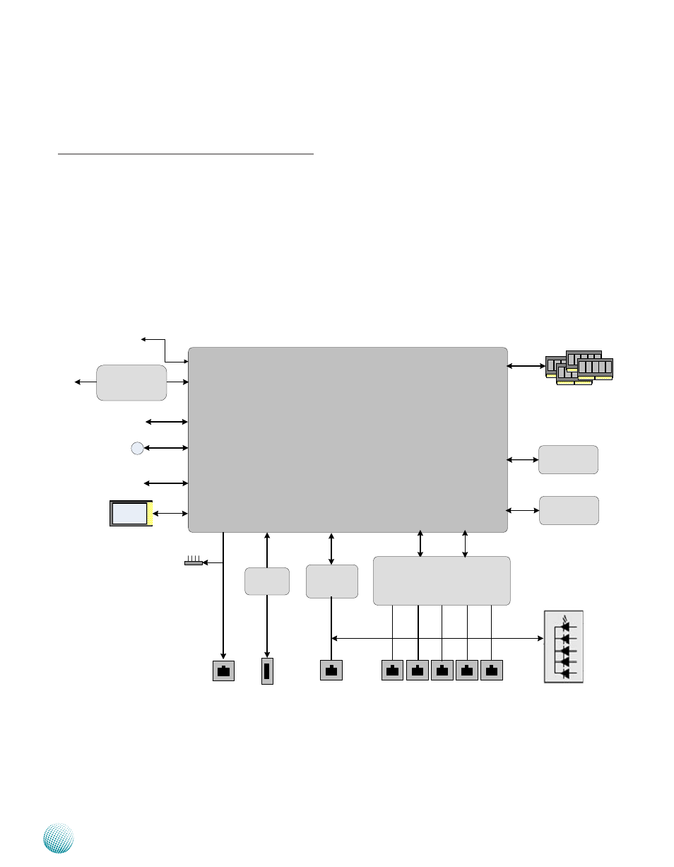
Block Diagram
The block diagram depicts the relationships among the
interfaces or modules on the motherboard. Please refer
to the following figure for your motherboard’s layout
design.
Freescale Single-Core P1011(MR-350A)
Freescale Dual-Core P1020 (MR-350B)
5 x GbE RJ-45 Connectors
RGMII
USB
connector
USB 2.0
Console
Debug port
JTAG
88E6171R
PCI-E
MiniPCI-E
(MR-350B only)
UART
RTC
I2C
RICOH
RS5C372A-E2-F
USB3300
RJ45
Console
Reset
Botton
4* x8 DRAM on board
Up to 1GB (SKU B),
SKU A up to 512MB
NAND
Flash
DDR3
32bit
256MB
NOR
Flash
2MB for Booting
RGMII
Front LED
Power/ Status / LAN
SD Socket
( MR-350B only)
SGMII
88E1111
(optional)
SATA HDD
(optional)
Reserved Only
See also other documents in the category Lanner Computer hardware:
- LVC-2000 (39 pages)
- LVC-5000(N4) (42 pages)
- LVC-5550S (41 pages)
- LVC-5570 (48 pages)
- LVC-5770 (49 pages)
- FW-6432 (16 pages)
- FW-7525 (41 pages)
- FW-5330 (38 pages)
- FW-6486 (18 pages)
- FW-6436 (19 pages)
- FW-7573 (44 pages)
- FW-7568 (52 pages)
- FW-7540 (47 pages)
- FW-8759 (47 pages)
- FW-7581 (23 pages)
- FW-8758 (42 pages)
- FW-7610 (44 pages)
- FW-8756 (24 pages)
- FW-7575 (48 pages)
- FW-8760 (53 pages)
- FW-8877 (46 pages)
- FW-8892 (58 pages)
- FW-8893C (49 pages)
- FX-3411 (48 pages)
- FW-8894 (31 pages)
- FW-8771 (47 pages)
- RS12-38800 (64 pages)
- MR-320 (20 pages)
- FX-3210 (54 pages)
- MR-301 (16 pages)
- MR-330A (16 pages)
- MR-730 (18 pages)
- VES-220 (19 pages)
- VES-270 (19 pages)
- VES-310 (15 pages)
- VES-310 V2 (20 pages)
- VES-500 (21 pages)
- EM-F345 (30 pages)
- VES-8X2 (16 pages)
- VES-8X6 (17 pages)
- LEC-2026 (67 pages)
- LEC-2010 (65 pages)
- LEC-2136 (20 pages)
- LEC-2050 (38 pages)