2 communications connectors (cn2), 3 led indicators – Yaskawa VS-606V7 User Manual
Page 11
3 Component Names and Settings
11
3.2
Communications Connectors (CN2)
The communications connectors connect the SI-T/V7 Unit to the communications lines of
the MECHATROLINK-I or MECHATROLINK-II . The following table shows the pin num-
bers and their functions.
3.3
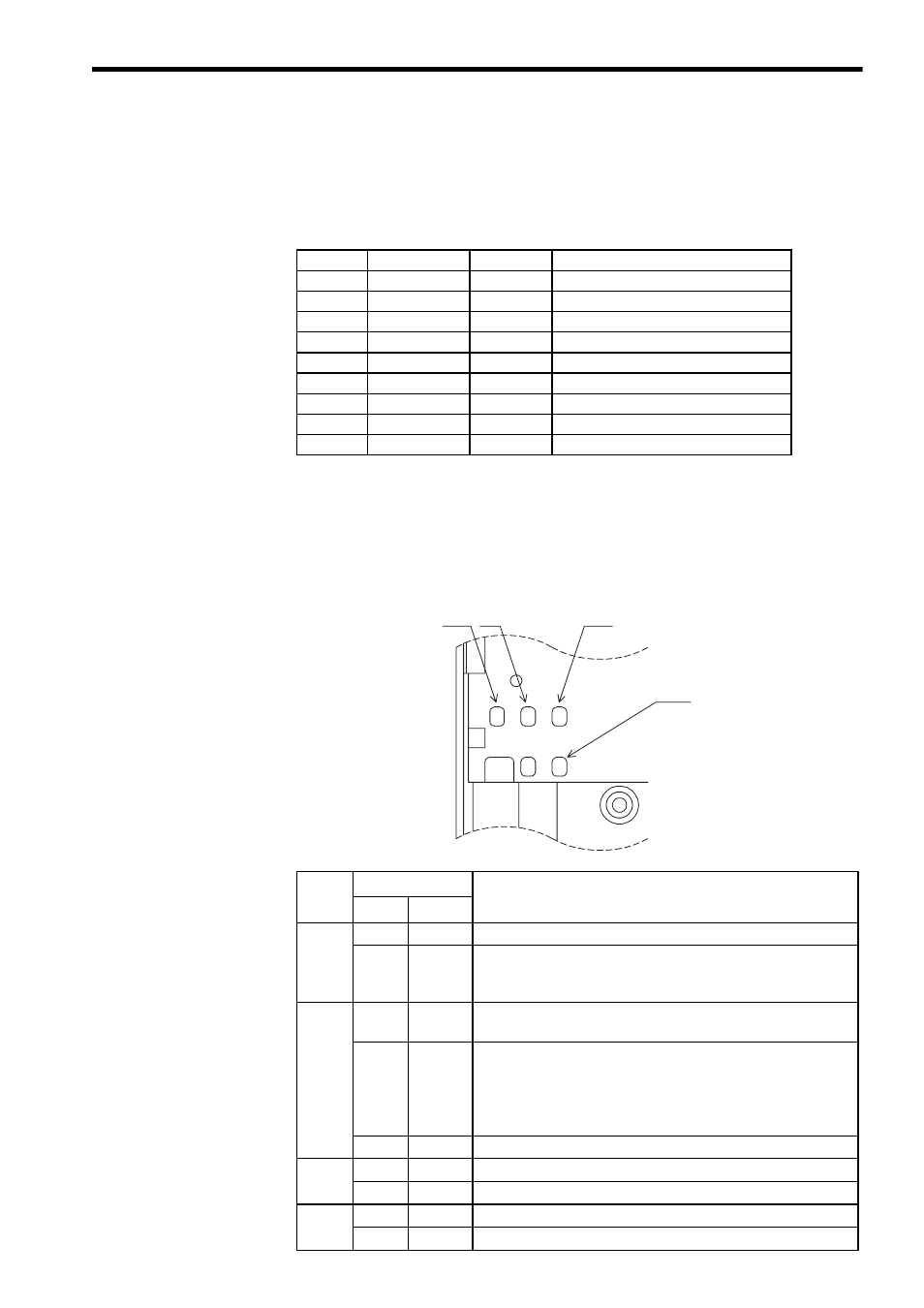
LED Indicators
The LED indicators indicate the status of the communications of the MECHATROLINK-I
or MECHATROLINK-II and the SI-T/V7 Unit.
However, these indicates are for maintenance checks at Yaskawa. Use the Digital Operator
to check the status.
Pin No.
Signal Name
I/O
Function
A1
(NC)
−
Not used.
A2
SRD
−
I/O
Send/receive data (-)
A3
SRD+
I/O
Send/receive data (+)
A4
(NC)
−
Not used.
B1
(NC)
−
Not used.
B2
SRD
−
I/O
Send/receive data (-)
B3
SRD+
I/O
Send/receive data (+)
B4
(NC)
−
Not used.
Shell
Shield
−
Not used.
Name
Display
Explanation
Color
Status
RUN
Green
Lit
Normal operation
−
Not lit
Communications CPU stopped, resetting hardware, RAM check
error, DPRAM check error, station address setting error, or
Inverter model code error
ERR
Red
Lit
Watchdog timeout error, communications error, or resetting hard-
ware
Red
Blinking
ROM check error (once), RAM check error (twice)*, DPRAM
check error (3 times)*, communications ASIC self-diagnosis error
(4 times) *, ASIC RAM check error (5 times), station address set-
ting error (6 times) *, Inverter model code error (7 times) *
*: Indicates the number of blinking.
−
Not lit
No communications error or self-diagnosis error
TX
Green
Lit
Sending data
−
Not lit
Sending of dara stopped, hardware reset
RX
Green
Lit
Searching for receiving carrier
−
Not lit
No receiving carrier found, resetting hardware
RUN TX
RX
ERR