5 installation procedure – Yaskawa V1000 Option - DI-100 120 Vac Interface User Manual
Page 15
5 Installation Procedure
YASKAWA ELECTRIC TOEP YEAOPT 03 - V1000 Option DI-100 120 Vac Interface Installation Manual
15
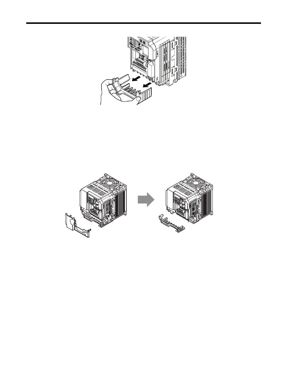
Figure 3
Figure 3 Remove Bottom cover
Note: Cover removal steps for larger models of V1000 with a Terminal Cover:
-Single-Phase 200 V Class: CIMR-VUBA0006 to BA0018
-Three-Phase 200 V Class: CIMR-VU2A0008 to 2A0069
-Three-Phase 400 V Class: All models
Note: Remove the terminal cover before removing the bottom cover to install the option. If the drive is
a NEMA Type 1 enclosure, then remove the lower conduit brackets.
Lower conduit bracket removal is not required for these larger models.
-200 V CIMR-VU2A0030F
thru CIMR-VU2A0069F
-400 V CIMR-VU4A0018F
thru CIMR-VU4A0038F
Figure 4
Figure 4 Models with Terminal Cover
3. Verify that the red color “CHARGE” indicator lamp (LED) inside the drive is off. It may take
as long as 10 min for the charge on the DC bus capacitors to drop to a safe level
4. Use a voltmeter to verify that the voltage at the incoming power terminals (R/L1, S/L2 and
T/L3) is not present and removed by disconnecting means.
5. Loosen terminals S1 ~ S7 and SC on V1000 drive control wiring terminal block TB1-1.