Yaskawa CM071 User Manual
Page 2
Yaskawa Electric America, Inc –
www.yaskawa.com
IG.AFD.17, Page 2 of 4
Date: 11/17/06, Rev: 06-11
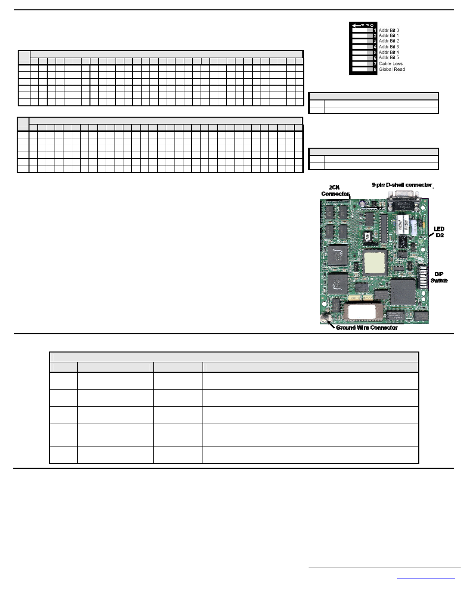
DIP Switch Settings
Set the Modbus Plus network node address
Set cable loss and global read behavior.
Modbus Plus Network Node Address
Sw
01 02 03 04 05 06 07 08 09 10 11 12 13 14 15 16 17 18 19 20 21 22 23 24 25 26 27 28 29 30 31 32
1 1 0 1 0 1 0 1 0 1 0 1 0 1 0 1 0 1 0 1 0 1 0 1 0 1 0 1 0 1 0 1 0
2 1 1 0 0 1 1 0 0 1 1 0 0 1 1 0 0 1 1 0 0 1 1 0 0 1 1 0 0 1 1 0 0
3 1 1 1 1 0 0 0 0 1 1 1 1 0 0 0 0 1 1 1 1 0 0 0 0 1 1 1 1 0 0 0 0
4 1 1 1 1 1 1 1 1 0 0 0 0 0 0 0 0 1 1 1 1 1 1 1 1 0 0 0 0 0 0 0 0
5 1 1 1 1 1 1 1 1 1 1 1 1 1 1 1 1 0 0 0 0 0 0 0 0 0 0 0 0 0 0 0 0
6 1 1
1
1
1
1
1
1
1
1
1
1
1
1
1
1
1
1
1 1 1 1 1 1 1 1 1 1 1 1 1 1
Modbus Plus Network Node Address
Sw
33 34 35 36 37 38 39 40 41 42 43 44 45 46 47 48 49 50 51 52 53 54 55 56 57 58 59 60 61 62 63 64
1 1 0 1 0 1 0 1 0 1 0 1 0 1 0 1 0 1 0 1 0 1 0 1 0 1 0 1 0 1 0 1 0
2 1 1 0 0 1 1 0 0 1 1 0 0 1 1 0 0 1 1 0 0 1 1 0 0 1 1 0 0 1 1 0 0
3 1 1 1 1 0 0 0 0 1 1 1 1 0 0 0 0 1 1 1 1 0 0 0 0 1 1 1 1 0 0 0 0
4 1 1 1 1 1 1 1 1 0 0 0 0 0 0 0 0 1 1 1 1 1 1 1 1 0 0 0 0 0 0 0 0
5 1 1 1 1 1 1 1 1 1 1 1 1 1 1 1 1 0 0 0 0 0 0 0 0 0 0 0 0 0 0 0 0
6 0
0
0
0
0
0
0
0
0
0
0
0
0
0
0
0
0
0
0 0 0 0 0 0 0 0 0 0 0 0 0 0
SW 7 – Cable Loss Detection
0 Disabled
1
Enabled
Note: G5HHP drive response is governed by parameters
F6-01, F6-02 and F6-03. Refer to the appropriate user,
programming or technical manual for parameter
information
SW 8 – Global Read Function
0 Disabled
1
Enabled
Connect the drive to the Modbus Plus communication network.
Connect the Modbus Plus network cable to the Modicon 9-pin D-shell connector.
● Recommended cable is Belden 9841
● Available Modicon cables
▪
97-9841-100 – Modbus Plus 100ft
▪
97-9841-500100 – Modbus Plus 500ft
▪
97-9841-01k100 – Modbus Plus 1000ft
● Modicon offers two connectors along with an assembly tool.
▪
AS-MBKT-085 – Modbus Plus In-line Connector
▪
AS-MBKT-185 – Modbus Plus Terminating Connector
▪
AS-MBPL-001 – Modbus Plus Connector Assembly Tool
● Assemble the cable to one of the connectors listed above. If this node is either at
the beginning or end of the network segment, use the terminating connector. For
all devices not at either end of the network segment, use the in-line connector.
Attach the Modicon connector to the 9-pin D-shell connector on top of the Modbus
Plus Option Card.
Apply power to the drive and verify that the diagnostic LED (D2) on the front of the Modbus Plus Option Card is in its correct state.
LED D2 States
Color
State
Timing
Description
Green
Continuous slow blinking
ON
OFF
340ms
640ms
Drive is off-line and cannot transmit. It does, however, listen on the network and
build an active node table
Green
Continuous rapid blinking
ON
OFF
80ms
80ms
Normal operation
Green
Two (2) rapid blinks
ON
OFF
160ms
160ms
Drive is permanently in the idle state and cannot be communicated with. Possibly a
bad transmitter
Green
Three (3) rapid blinks
ON
OFF
160ms
160ms
Drive cannot find any other nodes on the network. It claims and wins the token but
has nowhere to pass it, disrupting network communication. Possible network wiring
error
Green
Four (4) rapid blinks
ON
OFF
160ms
160ms
Duplicate node address found. Drive will stay off-line until the duplicate node
address has not been heard on the network for 5 seconds