Yaskawa GPD515-XXXX-CS004 User Manual
Page 3
Deleted Parameters:
The following parameters are no longer present, and their function descriptions in Section 5 of the
Technical Manual are not applicable:
b1-05
Zero-Speed Operation
b7-01 & b7-02
Droop Control Setup
b9-01 & b9-02
Zero Servo Setup
C3-05
Slip Compensation V/f
C5-01 thru C5-07
Automatic Speed Regulator
C8-08
AFR Gain
C8-30
Carrier in tune
d5-01 thru d5-06
Torque Control Parameters
E2-04, E2-06 thru E2-09
Open Loop Vector Parameters
F1-01 thru F1-14
Pulse Generator / Encoder Setup Parameters
L7-01 thru L7-04
Torque Limits
o1-03
Display Scaling
o1-04
Display Units
Startup Procedure:
1.
Set the Parameter Access Level to "Advanced" (Section 2.2C)
(2)
.
2.
Set the V/f pattern. This pattern can be a standard (preset) V/f pattern or a custom V/f
pattern. Preset V/f patterns can be found in Table 5-4 (Section 5.48)
(2)
. A preset V/f pat-
tern is selected by the setting of E1-03. When one of these preset V/f patterns is
employed, parameter E1-01 (Input Voltage Setting) needs to be set at the motor’s name-
plate value. If a custom V/f pattern is desired, set E1-03 = F (User Defined V/f) and use
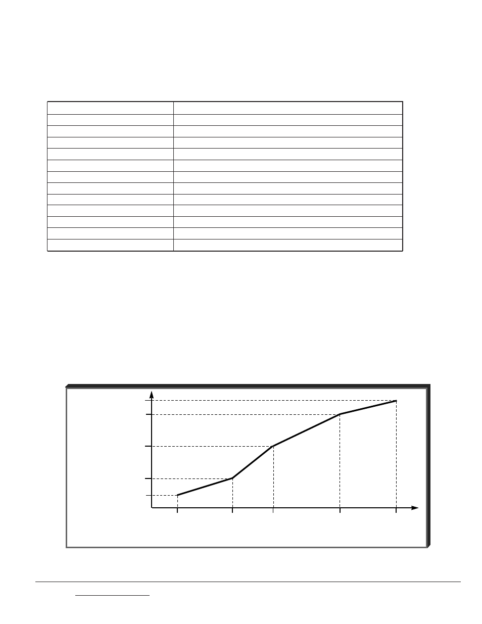
Figure 1 and parameters E1-04 thru E1-13 to set it up (Section 5.48)
(2)
.
Figure 1. V/f Characteristics Set by E1-04 thru E1-13
This Page: | Change | 0 | 4/18/97 |
Page 3 of 4
Doc. No. 02Y00025-0420
Vmax
( E1-05 )
V
B
( E1-12 )
Vbase
( E1-13 )
OUTPUT
VOLTAGE
V
A
( E1-08 )
Vmin
( E1-10 )
Fmin
F
A
Fbase
F
B
Fmax
( E1-09 )
( E1-07 ) ( E1-06 )
( E1-11 )
( E1-04 )
OUTPUT FREQUENCY