Yaskawa F7 Drive 1500 Hz Output User Manual
Page 2
Date: 05/05/05, Rev: 05-05
Page 2 of 7
TM.F7SW.056
This document is intended to provide proper installation and use of the Yaskawa drive with custom software. This
document is a supplement to the standard drive technical manual. It describes the effects on the drive parameters
and functions with the software installed. Read and understand this document and the standard drive technical
manuals before attempting to install, adjust, operate, inspect or maintain the drive. Observe all cautions and
warnings in this document and the standard drive technical manuals. Custom software is written to add
functionality to a standard AC drive to enhance or enable use in a specific application. The software is loaded to
the flash ROM area of the control board, and replaces the standard drive software. Custom software can add new
functions, modify standard functions, or even inhibit standard functions. It can be used to modify display text or
parameter names. Custom software is usually loaded to the drive before delivery. The control board and drive
nameplate are assigned unique part numbers and the software is registered, archived, and retrievable.
When seeking support for a drive with custom software, it is imperative to provide the unique part number shown
on the drive nameplate. The software has been flashed to the control board memory and the operation of
parameters, functions, and monitors are different than the standard drive software, as described herein.
1.0 Overview
This custom software is designed for high frequency motor (spindle) applications. The drive’s maximum output
frequency can be set to either 1000Hz or 1500Hz, depending upon C6-11. C6-11 is a factory level parameter
that can be accessed by setting A1-04 = 0616 (Password) and then setting A1-01 = 616 (Access Level). Do not
change any other factory parameters. Non-applicable drive functions have been deleted in order to optimize
CPU processing time for this software.
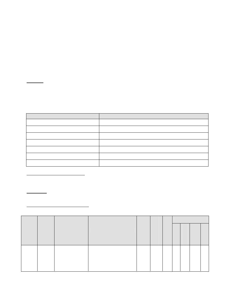
1.1 Basic Specifications
Item
Specification
Maximum Output Frequency
1000Hz (1500Hz when C6-11 = 1)
Control Mode
V/f without encoder feedback only (A1-02 = 0)
Drive Duty Rating
Normal Duty 1 only (C6-01 = 1). See section 6.3
Drive Overload
120% for 1 minute only
Drive Current Rating
See section 6.3
Carrier Frequency
10.0kHz maximum and default
Applicable Inverter Models
230V Class, 20P4 – 2090, 480V Class, 40P4 - 4160
2.0 Changes from Standard Product
a. The drive’s output current has been de-rated to allow for a higher carrier frequency.
b. Many of the drive’s standard features have been deleted.
3.0 Limitations
See section1.1.
4.0 Related Parameters and Functions
4.1 New Parameters
Control Mode *1
Paramete
r
Numb
er
Modbu
s
Addre
ss
Parameter Name
Digital Operator
Display
Description
Ran
ge
Default
Cha
nge
Duri
ng Run
V/f
V/f w/ PG
O
pen
Loop
Vec
tor
Flux
Vec
tor
C6-11 22DH
Frequency
Reference Limit
Unbal Det Sel
Sets the upper limit of the
maximum output
frequency (E1-04).
0: 1000Hz
1: 1500Hz
0 ~ 1
0
No F
-
-
-
*1: Access Level (A1-01): Q = “Quick Start”, A = “Advanced”, F = “Factory”.