Warning – Yaskawa GPD503 User Manual
Page 6
Refer to Sheet 1 for latest change.
DWG. NO. 02Y00025-0393
SHEET NO. 6 OF 10
R E L . 4 / 2 6 / 9 6
INSTALLATION
Preliminary Procedure
WARNING
HAZARDOUS VOLTAGE CAN CAUSE
SEVERE INJURY OR DEATH.
LOCK ALL POWER SOURCES
FEEDING DRIVE IN “OFF” POSITION.
1.
Disconnect all electrical power to drive.
2.
Remove drive front cover.
3.
Verify that voltage has been disconnected by
using a voltmeter to check for voltage at the incoming
power terminals.
Mounting and Wiring Units
IMPORTANT
Since the braking resistor unit generates heat
during dynamic braking operation, install it in a
location away from other equipment which
emits heat.
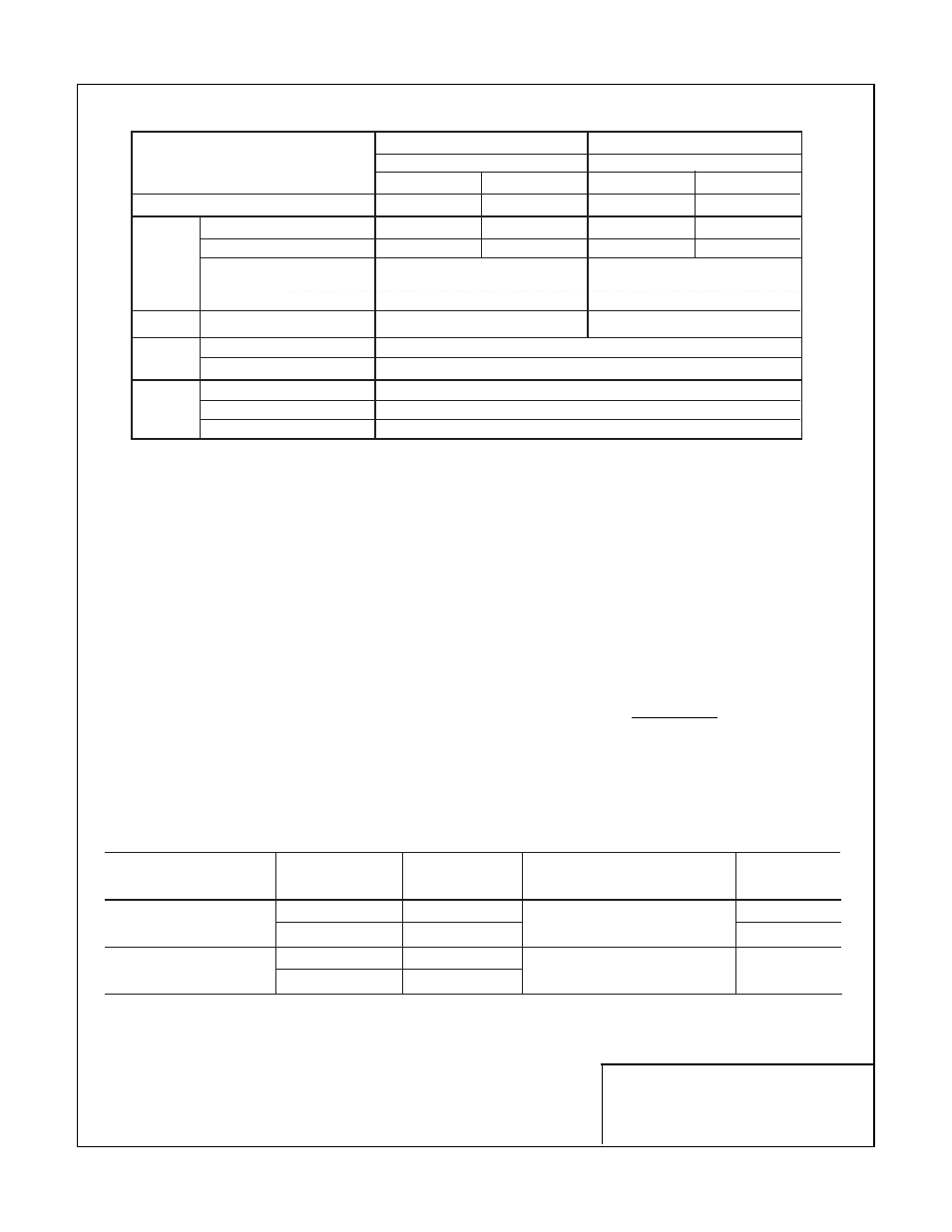
Table 3
LEAD SIZE
LEAD
TERMINAL
UNIT
TERMINALS
(AWG)
TYPE
SCREWS
Braking Resistor Unit
B, P
12-10
600V ethylene propylene
M5
1, 2
✱
18-14
✱
rubber insulated or equiv.
M4
Braking Unit
P, Po, N, B
12-10
600V ethylene propylene
M4
1, 2
✱
18-14
✱
rubber insulated or equiv.
✱
Power leads for the braking resistor unit generate high levels of electrical noise; these signal leads must
be grouped separately.
Table 2. Specifications of Braking Units
230V
460V
Item
Part Number
Part Number
46S03331-0010 46S03331-0020 46S03331-0050 46S03331-0060
Max. Motor Output Capacity HP (kW)
20 (15)
30 (22)
40 (30)
60 (45)
Max. Current * (A) (peak value)
40
60
40
60
Rated Current (A) (RMS value)
15
20
15
18
Turn-on Level
• 330/345/365/380 VDC (±3V)
• 630/660/690/730/760 VDC (±6V)
• Master/Slave Control Available
• Master/Slave Control Available
Hysteresis (V)
Approx. 5 VDC
Approx. 10 VDC
Bus Voltage
243 VDC – 400 VDC
460 VDC – 800 VDC
Overheat Protection
By Thermoswitch
Output (N.O. contact): AC 250V, 2A; DC 30V, 2A
Charge Indication
“CHARGE” lamp stays on until DC voltage drops below 50 VDC
Location
Indoor; protected from corrosive gas and dust
Ambient Temperature
-10 to +40°C (+14 to +104°F) (not frozen)
Storage Temperature
-20 to +60°C (-4 to +140°F)
OUTPUT
RATINGS
POWER
SUPPLY
PROTECTIVE
FUNCTIONS
ENVIRON-
MENTAL
CONDITION