Appendix a, Specifications, parts, and accessories, Appendix a • specifications, parts, and – Extron Electronics DVI DL 101 User Manual
Page 15: Accessories
DVI DL 101 • Installation and Operation
Installation and Operation, cont’d
2-16
DVI DL 101
A
Appendix A
Specifications, Parts, and
Accessories
Specifications
Included Parts
Optional Accessories
Cables and Adapters
5
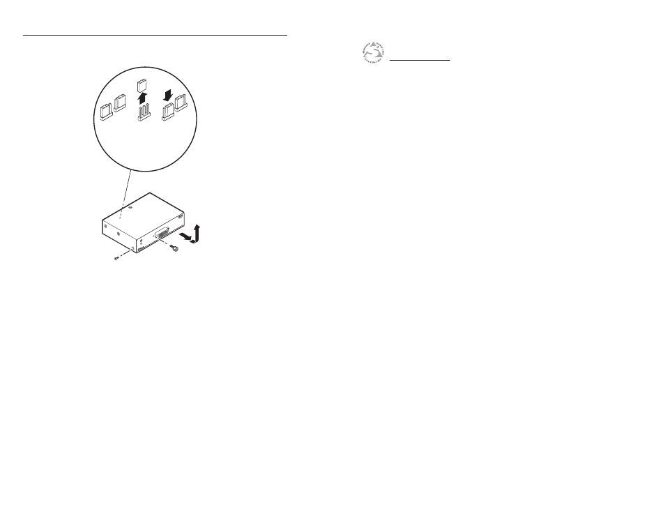
.
Lift each jumper off its pins and slide it down onto the
inside
and middle pins. See the illustration below.
DVI-DUAL LINK INP
UT
DVI DL 101
Jumper Pin Sets J4 and
J5 Inside Unit
DDC Buffer
Bypassed
(Default)
DDC Buffer
Enabled
Jack Screw
Nut
Remove screws from
sides and top (7).
Slide forward,
then up.
6
.
Replace the top cover onto the unit, and slide it back until
the DVI input connector protrudes through its slot in the
front panel.
7
.
Replace the two jack screws and the seven Philips screws
that you removed in step 1.
This manual is related to the following products: