Power, Ps5010, Ps5000 – Grass Valley Viper II User Manual
Page 3
Power
The PS5000 features an AC Power Entry
Module that allows the user to set up the
unit to work within their local power
requirements. AC line voltage is supplied
to the rear of the module with a standard
IEC/NEMA type power cord. A window on
the Power Entry Module reflects the
current VAC setting of either 115 or 230V.
Verify that the voltages on the units are set
properly before operating the system. If the
input voltage must be changed, use the
following procedure:
1. Use a small, flat-blade screwdriver in
the notch at the top of the module to
gently pry open the module cover and
expose the fuse block. The cover is
hinged at the bottom and will open
easily.
2. Gently pop out the fuse block.
3. Turn the block over and replace it back
into the module.
4. Close the module cover.
The new input voltage value will be
reflected in the voltage value window.
The same procedure is followed for fuse
replacement. Be careful to use ONLY
1Amp SLO-BLO fuses, 5 x 20mm.
Operation of the 115/230 VAC Power
Entry Module
General
The PS5000 serves as the primary power
supply for the Viper II frame. It is a double-
wide module that can be positioned
anywhere amongst the 16 slots of the
frame. Input power requirements are 100-
240VAC. A full frame will draw no more
than 750mA.
The PS5000 and the PS5010 are inserted
into the frame in the same way as any
other Viper II module however, due to the
extra weight of these modules, extra care
should be taken to ensure that they are
aligned properly.
Operation
Once the module is configured to your
local power, it is ready for use. There are
power switches on both the Power Entry
Module (PEM) and on the faceplate of the
module. If the PEM power switch is not in
the on position, the faceplate switch will
not function.
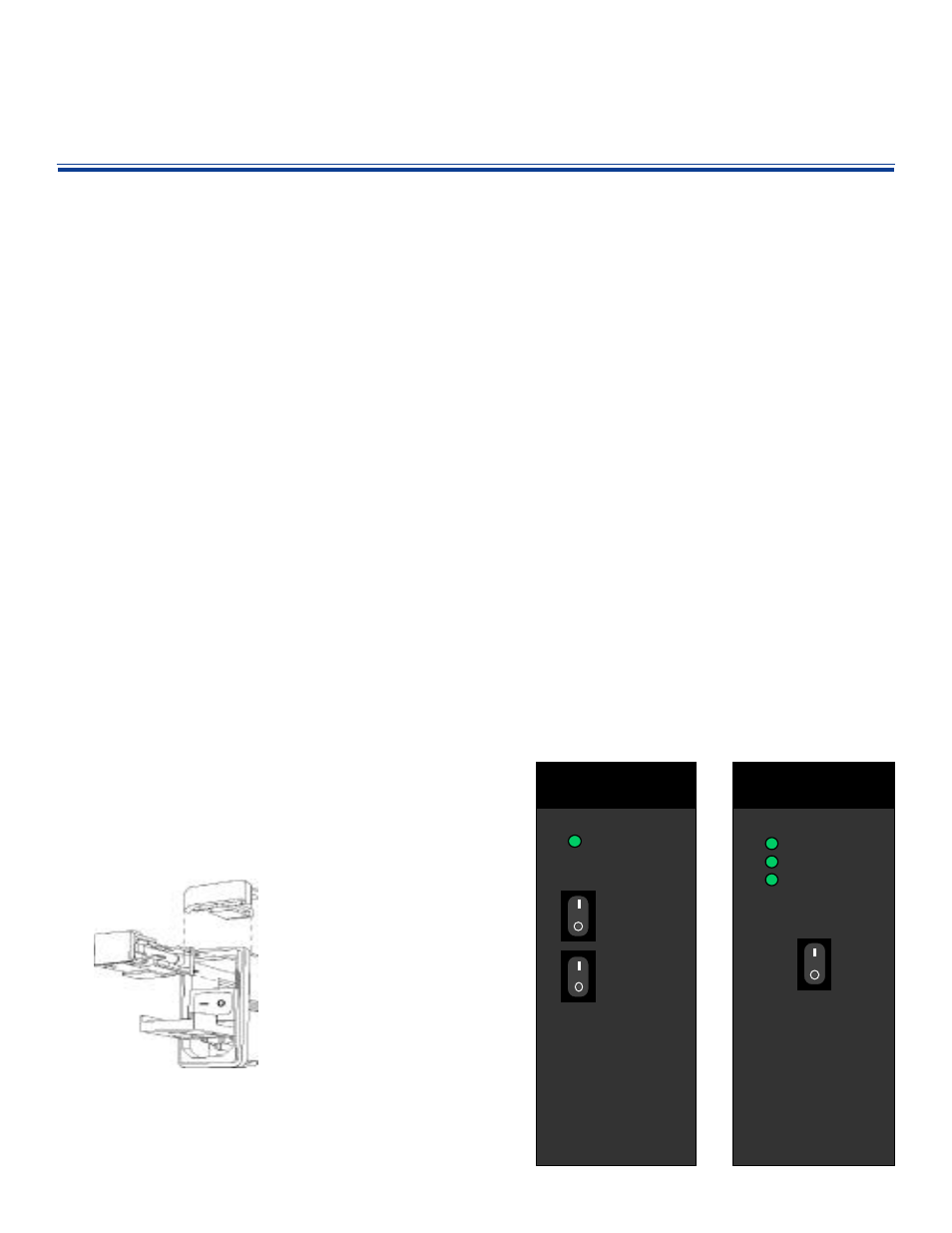
With the main switch "on" the faceplate
switches now becomes operational. When
the faceplate switch is in the "on" position,
the LED's will indicate the condition of both
the PS and the Power Bus of the frame:
For the PS OK LED, green indicates that it
is receiving AC line voltage and that input
voltage is within acceptable parameters.
The PS ACTIVE LED will turn green to
indicate that the PS is generating DC
voltage and sending it to the power bus.
The BUS LED monitors the voltage on the
power bus and will turn green to indicate
that 12-18VDC is present.
If any of the LEDs are red, then a fault
condition exists. Make sure that the power
entry module is set correctly. If so, then
check the backplane for bent pins. If there
are no obvious problems, contact Telecast
for an RMA number.
If the BUS LED turns
orange, indicating a DC
output between 10-12 VDC,
then you have either:
1. low input voltage
2. A power bus short or
3. A faulty functionality
module that is drawing
too much power.
Troubleshoot this by first
verifying proper input
voltage. Then check to
ensure that there are no bent
pins on the backplane. If the
fault persists, remove other
functionality modules, one by
one, to try to isolate the
excess power draw to a
single module.
If a functionality module is
found to be the source of the
problem, contact Telecast for
an RMA number.
The PS5010 Battery Back-Up
When inserted into the frame, the PS5010
will supply up to 30 minutes of back-up DC
power in the event of a power failure. This
is accomplished through the use of two
banks of Ni-Cad batteries. All rules
concerning Ni-cads and "charge memory"
apply. If you find that your PS5010 is no
longer holding a sufficient charge, call
Telecast for an RMA number.
The PS5010 unit has two switches:
BATTERY
Turns the unit on and off
ALARM
When in OFF position,
this defeats the alarm
that would sound to
indicate an interruption
of mains power.
There is a single LED on the faceplate
indicating the STATUS of the unit:
RED
Discharging
GREEN
Charging
Note that if the BATTERY switch is left in
the ON position but the PS5000 is turned
OFF, the PS5010 will discharge until
dead.The STATUS LED will be RED to
indicate this discharge condition. When-
ever powering down the frame, be sure to
switch both the PS5000 and the PS5010 to
the OFF position.
PS5010
STATUS
ALARM
BATTERY
BATTERY BACKUP UNIT
PS5000
POWER SUPPLY UNIT
POWER
PS OK
PS ACTIVE
BUS