Viper ii rack – Grass Valley Viper II User Manual
Page 2
Viper II Rack
The Viper II rack Frame (V2) is a 19" 3 RU
card cage designed to house the entire
line of Telecast Viper II modules. Each
frame has 16 slots that can be used to
accommodate both single and double-slot
modules and power supplies. Assuming
two slots for the main PS5000 power
module, the user is left with 14 slots for
functionality modules with the option of
adding multiple PS5000 or PS5010 Battery
Back-Up power modules for further
insurance against power outages.
The V2 frames uses a power bus system
using the "Future-Bus 24-pin header"
giving the user flexibility in the placement
of modules in the frame. The pinout for the
Future-Bus connector is shown at right.
The frame features a hinged front security
bar that is used to secure the modules.
The bar is locked down using the two
spring-screws located on each side of the
hinged panel.
General
Unpacking
To ensure that no damage occurs to the
V2 frame during shipment, it is packed and
shipped without modules inserted. Care
should be taken when removing it from its
packing materials. Inspect the unit closely
for loose screws, smooth hinge operation,
missing nylon card guides and/or cosmetic
damage. Any problems should be reported
to Telecast immediately.
To return an item for repair, call Telecast at
508-754-4858 to obtain a return material
authorization (RMA).
Note that the frames undergo an alignment
procedure during assembly and testing.
Any movement of the backplane will result
in the possibility of damaged pins in the
power connectors. Do not make adjust-
ments to the position of the backplane
panel!
Rack ears are included with the frame and
are shipped attached.
Caution should be taken to ensure that the
hinged security bar is up and in the locked
position when modules are not being
installed. Failure to do so may result in
modules falling out of the frame if it were to
be inadvertantly tilted or moved.
Installing Modules
Converting "Throw-Down" Modules
The Future-Bus Connector
GND
10-18VDC
Reserved
DC power is
supplied to the
frame via a 24-
pin "Future-Bus"
connector. When
looking into the
frame, the pin-
outs are as
indicated in the picture to the right. The top
two rows of 4 pins are 0V Ground. The
middle two rows are for 10-18VDC OUT
and the last two rows are reserved for
future expansion of the Viper II system.
CAUTION: Care should be taken when
inserting and removing modules as these
pins are of a very fine pitch and can easily
be bent. If pins do become bent, contact
Telecast for an RMA number as it is not
recommended that the user attempt a
repair as failure to properly align the
backplane will result in additional bent
pins.
The installation and removal of modules is
a very straight-forward process but, as
mentioned above, care should be taken to
ensure that no damage occurs as a result
of an improperly inserted module.
Each frame is equiped with nylon card
guides for each of the 16 slots. In cases
where the module is two spaces in width,
only the left-side guide is used.
Carefully align the module in the top and
bottom guides and slowly insert it. As the
rear end of the module nears the rear of
the frame, it will hit a riser-plate that serves
to lift the module so that the power
connectors will properly come together and
seat. You will "feel" this plate as you insert
the module and as you continue to insert it
you will "feel" the female power connector
on the module make smooth contact with
the male power plug in the frame. Any
attempts to 'slam' the module into the
frame is likely to result in bent pins.
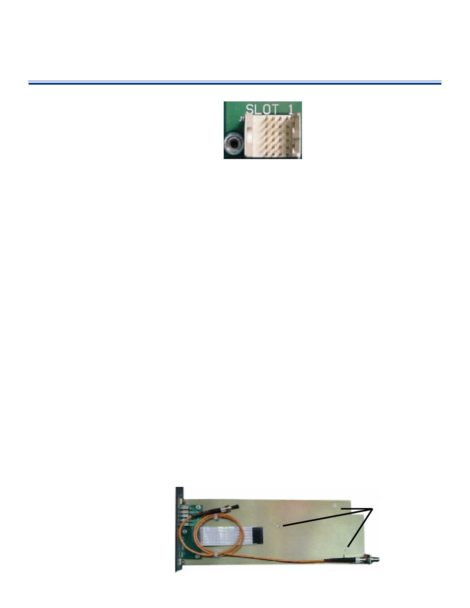
Any of the Telecast Viper II "throw-down"
modules can easily be converted to fit in a
Viper II frame. A Rack Mount Kit (RMK) is
all that is required to make such a conver-
sion. As the picture below illustrates, the
kit includes a metal spline with ST barrel, a
short ST-ST jumper cable and the frame
faceplate with a ribbon cable to transfer
LED indicator information from the module
to the new faceplate.
Installation involves removing the back
cover from the throw-down module. It is
secured with three machine screws. Once
the rear plate is removed, the module
simply installs onto the new spline with the
same three screws.
If you are converting a digital module, care
should be taken to ensure that the EMI
gasketing remains in position as the back-
plates are exchanged. Failure to do so
may increase the probability of RF/EMI
leakage from the module. Care should
also be taken in connecting the ribbon
cable and in the routing of the fiber jumper.
A pinched or too-tightly-coiled jumper
could impede optical performance.
Relevant Part Numbers
V2Frame-1
3 RU Viper II Cage
PS5000
Power Supply
PS5010
Battery back Up
RMK-XXXX
Rack Mount Conversion
Kit. Contact Telecast for
Specific Model Numbers
BP5001
One-wide Filler Panel
BP5002
Two-Wide Filler Panel
11000-054
Throw-Down Back Plate
When making this conversion, be sure
keep the old back-plate in a safe place for
future re-conversion back into the throw-
down configuration.
Note the three holes
used in securing the
module to the spline
and the ST fiber
jumper and ribbon
cable that must be
attached.