Grass Valley Trinix Back-Up Power Supplies Apr 13 2010 User Manual
Page 40
40
Trinix — Back-Up Power Supplies Installation Manual
Section 5 — Installation
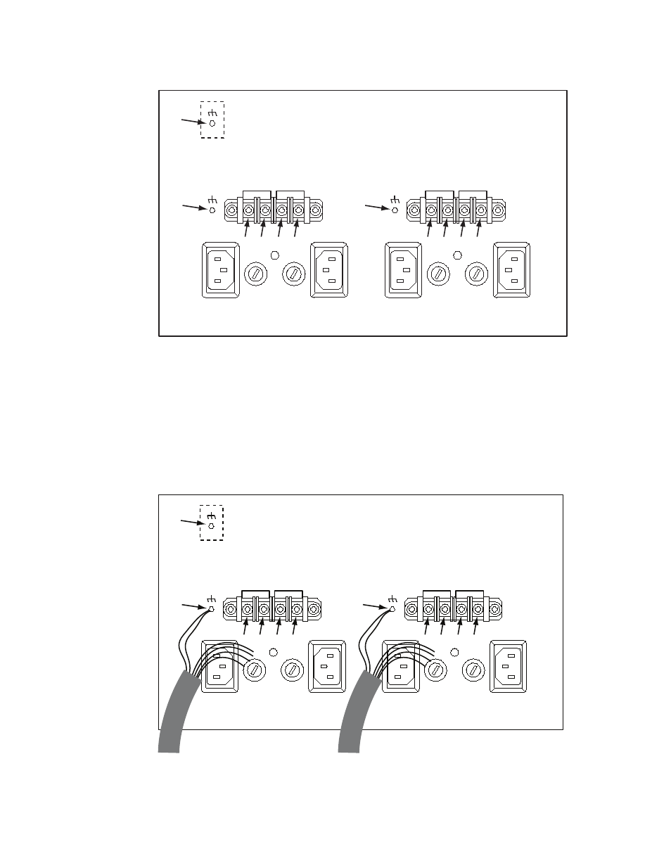
Figure 5. DV-33512 Power Supply Connectors Showing Reference Numbers Used in this Document
DC IN -
DC IN +
PS B
PS A
DC IN -
DC IN +
PS D
PS C
(1)
(2)
(7)
(3)
(4)
(5)
(6)
(8)
(9)
(10) (11)
c.
Remove the “DC IN +” and “DC IN -” screws (3), (4), (5), (6), (8), (9),
(10), and (11).
d.
Locate the two DC power ground studs (2) and (7). Use a nut driver
to remove one nut (only) and one washer (only) from each stud.
e.
Connect the supplied jumper wires and external power supply
cables as shown in
and
.
Figure 6. Jumper and External Power Supply Wiring (Partially Complete)
DC IN -
DC IN +
PS B
PS A
DC IN -
DC IN +
PS D
PS C
(1)
(2)
(7)
(3)
(4)
(5)
(6)
(8)
(9)
(10) (11)
to external A/B power supply(s)
to external C/D power supply(s)
- LDK 5302 (24 pages)
- SFP Optical Converters (18 pages)
- 2000GEN (22 pages)
- 2011RDA (28 pages)
- 2010RDA-16 (28 pages)
- 2000NET v3.2.2 (72 pages)
- 2000NET v3.1 (68 pages)
- 2020DAC D-To-A (30 pages)
- 2000NET v4.0.0 (92 pages)
- 2020ADC A-To-D (32 pages)
- 2030RDA (36 pages)
- 2031RDA-SM (38 pages)
- 2041EDA (20 pages)
- 2040RDA (24 pages)
- 2041RDA (24 pages)
- 2042EDA (26 pages)
- 2090MDC (30 pages)
- 2040RDA-FR (52 pages)
- LDK 4021 (22 pages)
- 3DX-3901 (38 pages)
- LDK 4420 (82 pages)
- LDK 5307 (40 pages)
- Maestro Master Control Installation v.1.5.1 (455 pages)
- Maestro Master Control Installation v.1.5.1 (428 pages)
- 7600REF Installation (16 pages)
- 7600REF (84 pages)
- 8900FSS (18 pages)
- 8900GEN-SM (50 pages)
- 8900NET v.4.3.0 (108 pages)
- Safety Summary (17 pages)
- 8900NET v.4.0.0 (94 pages)
- 8906 (34 pages)
- 8911 (16 pages)
- 8900NET v.3.2.2 (78 pages)
- 8914 (18 pages)
- 8912RDA-D (20 pages)
- 8916 (26 pages)
- 8910ADA-SR (58 pages)
- 8920ADC v.2.0 (28 pages)
- 8920ADC v.2.0.1A (40 pages)
- 8920DAC (28 pages)
- 8920DMX (30 pages)
- 8920ADT (36 pages)
- 8920MUX (50 pages)
- 8921ADT (58 pages)