Grass Valley Trinix Multiviewer Quick Start User Manual
Trinix multiviewer quick start guide, Trinix multi-viewer (tmv) connections, Download the latest documentation
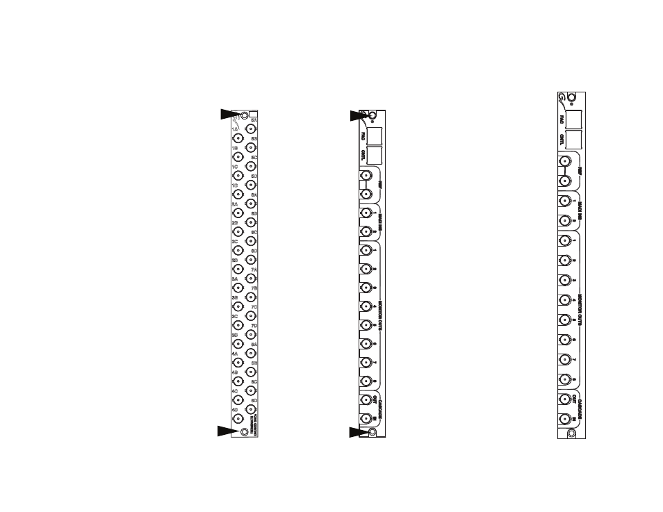
Trinix Multiviewer Quick Start Guide
LAN
Connections
Reference
Connections
Discrete Audio
Connections
Monitor
Connections
Trinix Multi-Viewer
(TMV) Connections
Cascading
Connections
Part # 071881500
Download the latest
Documentation
Please download the latest documentation
from the Grass Valley Web site.
Install the TMV Boards in
the correct Output Location
The TMV board must be installed in the
following Output ranges:
256X512
Jupiter: 128-159, 160-191, 192-223, 224-255,
256-287, 288-319, 320-351, and 352-383
Encore: 129-160, 161-192, 193-224, 225-256,
257-288, 289-320, 321-352, and 353-384
128X128*
Jupiter: 0-31 and 64-95 only
Encore: 1-32 and 65-96 only
256X256*
Jupiter: 0-31, 64-95, 128-159, and 192-223
Encore: 1-32, 65-96, 129-160, and 193-224
512X512*
Jupiter: 0-31, 64-95, 128-159, and 192-223
Encore: 1-32, 65-96, 129-160, and 193-224
A TMV board may be placed in any Output
slot for the 128x256 and the 512x1024 Trinix
Routing switchers.
* For optimum power and thermal efficiency,
each TMV board in a 128x128, 256x256 or
512x512 Trinix Frame requires two slots; one
slot for the board and an empty adjacent slot.
Follow Grass Valley’s recommended ESD
guidelines as explained in the
TMV Installation and Service Manual.
Installing the Trinix Multiviewer
Remove the top and bottom
screw for the rear Output panel.
Remove the rear Output panel and
Place the TMV rear panel into
the Output slot.
Fasten the TMV rear panel to the frame
using the provided screws.
From the front of the Trinix frame,
insert the TMV boards into their
corresponding locations and then
lock them into place.