Signal connectors, Dip switches, Signal connectors dip switches – Grass Valley NV8900 Series v.1.3 User Manual
Page 15: Config
7
NV8900
User’s Guide
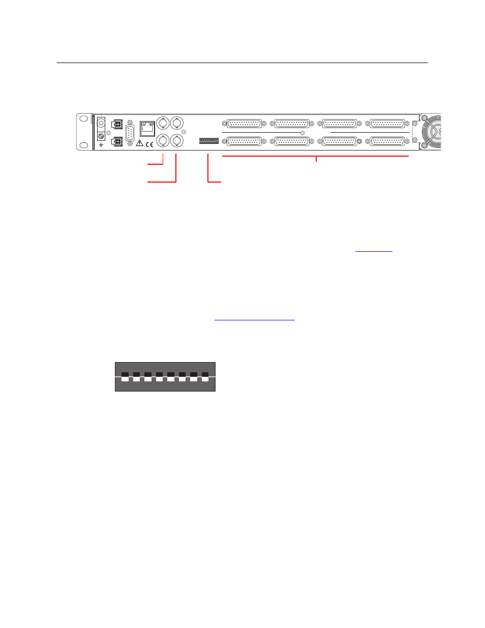
Signal Connectors
At the rear of the AA-to-MADI interface are signal connectors. There are 2 MADI outputs (BNCs),
two video reference connectors (BNC, loop-through), and 8 DB25s for analog audio input.
Each DB25 supports 8 analog audio inputs. The 8 inputs on a connector correspond to an
enclosed section of the labeling on the front of the unit. For instance, first DB25 connector is for
inputs 1 through 8 and the corresponding markings on the front of the unit are pair 1/2, 3/4, 5/6,
and 7/8.
The power connectors, serial port, and Ethernet port are described under
Each power connection is represented by an LED at the front of the unit. When the LED is green,
its power supply circuit is good. If the LED is off, the power supply is bad.
The MADI outputs are identical.
The video reference connectors are “loop-through” allowing you to “daisy-chain” a reference
signal to multiple devices. See
DIP Switches
There are 8 DIP switches in a recess at the rear of the unit:
The first 3 switches control the overall audio level of the unit:
Switch
Switch
3
2
1
Level
3
2
1
Level
0
0
0
+24 dBu
1
0
0
+16 dBu
0
0
1
+22 dBu
1
0
1
+14 dBu
0
1
0
+20 dBu
1
1
0
+12 dBu
0
1
1
+18 dBU
1
1
1
+10 dBu
Switches 4–7 are reserved for future use. It does not matter which way these switches are set.
Switch 8 is for factory testing. Leave it off.
1
ON
2 3 4 5 6 7 8
SDO8
CTRL
PS1
PS2
DC IN
+12V
E146905
ETHERNET
MADI OUT VID REF
CONFIG
41-48
49-56
ANALOG AUDIO
INPUTS
25-32
17-24
9-16
1-8
57-64
33-40
Analog Inputs (DB25)
Video Reference
(Loop-Through)
MADI Output (2)
DIP Switches (8)
1
ON
2 3 4 5 6 7 8
SDO8
CONFIG