Nv920 control system – Grass Valley NV920 Nov 26 2014 User Manual
Page 5
Product Number: QG0014-03 Revision: A0; Date: 11/26/14
5
NV920 Control System
Referring to Figure 5, follow these steps to make system con-
troller connections:
1) Connect routers to the system controller.
Connect an Ethernet switch to either or both of the panel
and router network ports on system controller 1. (In Figure
5, those are NVNET 1 and NVNET 2.) Do the same for sys-
tem controller 2 if you have one.
A router might have both a primary and secondary control
card for redundancy. Either or both may connect to a
panel and router network.
Note that the Ethernet switches are cross-connected in a
redundant system:
The cross-connection allows either controller to commu-
nicate with any panel or router. In a non-redundant sys-
tem, the cross-connection is not necessary.
2) Connect physical control panels to the system controller
using the same Ethernet switches. (Software control pan-
els are treated separately and differently.)
The NV9000 system uses DHCP to assign a panel’s IP
address whereas the IP addresses of router control cards are
fixed.
Each physical control panel must have a unique panel ID.
You must set the panel IDs. The method is different for
each physical panel. Refer to panel documentation or call
Grass Valley customer support. (Note that a panel ID is not
an IP address.)
Virtual control panels (a separately purchased option) can
be installed on your PCs. Each virtual panel also has a
panel ID. The installation method is the same for all vir-
tual panel types. Refer to the virtual panel documentation.
Panel IDs are important in the configuration software.
A Panel/Router Network and a Master Control Network
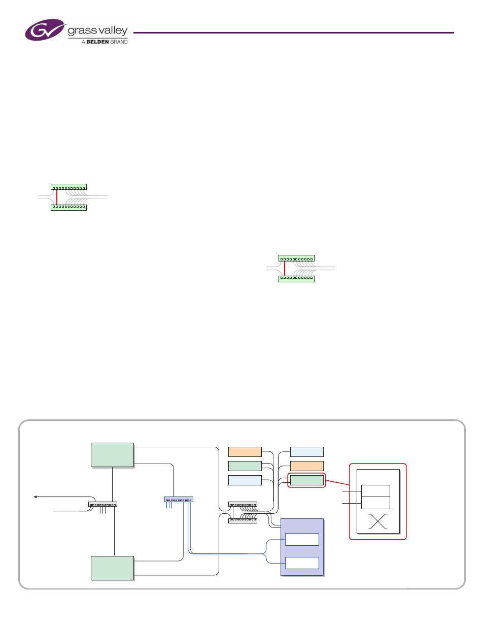
Figure 6, below, diagrams a redundant system that uses
•
NVNET 1 for a network of panels and routers
•
NVNET 2 for a master control network
•
NVNET 3 for configuration and monitoring. (If your sys-
tem has a single system controller, please disregard con-
troller 2 in the diagram and any connections to it.)
This guide does not address master control planning and setup.
Consult Grass Valley customer support or obtain master control
documentation from the Grass Valley website if you need a master
control system.
Referring to Figure 6, follow these steps to make system con-
troller connections:
1) Connect routers to the system controller.
Connect an Ethernet switch to the panel and router net-
work on system controller 1. (In Figure 6, that is NVNET 1.)
Do the same for system controller 2 if you have one.
Note again that the Ethernet switches are cross-connected
in a redundant system:
The cross-connection allows either controller to commu-
nicate with any panel or router. In a non-redundant sys-
tem, the cross-connection is not necessary.
2) Connect physical control panels to the system controller
using the same Ethernet switches. (Software control pan-
els are treated separately.)
3) Connect master control devices to the system controller.
Master control devices include MCEs, MCPMs, Imagestore
750s, and control panels (such as the iMC-Panel-100).
Connect an Ethernet switch to NVNET 2 (for master con-
trol) on system controller 1. Do the same for system con-
troller 2 if you have one.
Figure 6. Connections for a Redundant NV920 — a Panel and Router Network and a Master Control Network
NVNET 1
NVNET 2
NVNET 2
House Net
NV9000
GUIs
NVNET 1
M.C. Panels,
Config. PCs,
GUIs
Master
Control
NV5100MC
Tally
Config.
PCs,
GUIs
MCE 1
NV Router
Tally
Router
Router
Prim. Ctrl.
Sec. Ctrl.
Panel
Panel
NVNET 3
NVNET 3
MCE n
NV920
Controller 1
NV920
Controller 2
Panels and
Routers