Nv920 control system, Part 2: make connections to the system controller – Grass Valley NV920 Nov 26 2014 User Manual
Page 4
4
Product Number: QG0014-03 Revision: A0; Date: 11/26/14
NV920 Control System
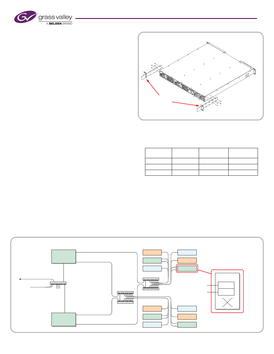
Follow these steps to mount the NV920:
1) Locate the mounting hardware attached to the side of the
NV920 frame. There are two metal parts for each side of
the frame. Unscrew the metal parts from the frame.
2) Referring to Figure 4, attach the two small parts (with the
slot) to the posts at the rear of the frame at the height at
which you will install the frame.
3) Reattach the two long parts to the frame so that they will
extend into the slots of the small parts at the rear of the
frame. Again, refer to Figure 4.
4) Now move the frame into position, with its support exten-
sions sliding into the slots of the supports at the rear of the
frame.
Attach the front of the frame to the front posts of the
frame using appropriately sized screws.
5) Insert power supply module(s) and system controller(s).
6) Use the supplied power cords to connect power. The con-
troller’s power supplies accept 100–240VAC, 47–63 Hz).
UL caution: to reduce the risk of electric shock, plug each power
supply cord into separate branch circuits employing separate
service grounds. Redundant power connections, of course, pro-
vides additional protection against failure.
If the NV920 frame emits an alarm tone, press the red button
next to the power supplies at the rear of the frame.
Caution: If you disconnect power without first shutting down
the system controllers, you risk corrupting system data. Before
disconnecting power, press the ‘Power Down to Remove’ button
of each system controller of the frame. Wait for the system con-
trollers’ LEDs to turn off. Then disconnect power.
Part 2: Make Connections to the System Controller
The additional units that compose the NV9000 control sys-
tem
—
PCs, control panels, routers
—
communicate through
the active system controller. The system controller uses
Ethernet to communicate
with system components.
Each of the NV920’s ports has a unique IP address, fixed inter-
nally. The IP addresses depend on whether the system con-
troller is stand-alone or redundant:
You may change any of these addresses to match your facility’s
networks.
Example: Two Networks for Panels and Routers
Figure 5, below, diagrams a redundant system that uses two
Ethernet ports for panels and routers and the third port for
configuration and monitoring. (If your system has a single
system controller, please disregard controller 2 in the dia-
gram and any connections to it.)
Port
Single
Controller
Redundant
Controller 1
Redundant
Controller 2
NVNET1
192.168.1.1
192.168.1.1
192.168.1.2
NVNET2
192.168.2.1
192.168.2.1
192.168.2.2
NVNET3
192.168.3.1
192.168.3.1
192.168.3.2
Figure 5. Connections for a Redundant NV920 — Two Panel and Router Networks
NVNET 1
NVNET 2
House Net
NV9000
GUIs
NVNET 2
Tally
Config.
PCs,
GUIs
NV Router
NV920
Controller 1
Tally
Router
NVNET 1
Router
Prim. Ctrl.
Sec. Ctrl.
Panel
Panel
Tally
Tally
Router
Router
Panel
Panel
NVNET 3
NVNET 3
NV920
Controller 2
Panel
and
Router
Networks
Figure 4. Frame Support
Attach to rear
rack posts.
(front of unit)