Typical system, Signal processor frame installation – Grass Valley 1200 Installation Planning Guide User Manual
Page 4
Preview
Monitor
MODEL 1200
SWITCHER
Primary Inputs
DPM-700
DIGITAL PICTURE
MANIPULATOR
Still Store
Character
Generator
Component Digital
Video Tape
Recorder (VTR)
Analog
Key Out
Clean Feed Out
CH. 1 In
Key Out
Analog
Video Tape
Recorder (VTR)
Analog
Video Out
TYPICAL VIDEO SOURCES
Component
Digital Video
Out
Component
Digital Key
Out
Component
Digital Video
Out
Analog
Video Out
Analog
Video Out
Camera
Aux 1
or
Send
Key
Aux 2
or
Send
Video
CH. 2 In
Effects Send Return Path
Analog Program Out
Program Key Out
Program
Monitor
Digital
Record VTR
Analog PVW Out
Digital Program Out
Clean Feed Out
Periph Port
DPM
Port
Null Modem Cable
(054714-03)
A to D
A to D
A to D
A to D
Model
1
200
D
I
G
I
T
A
L
Keyboard
EXT REF IN
EXT. REF. INPUT
(LOOPING)
External Reference
Analog Color Black
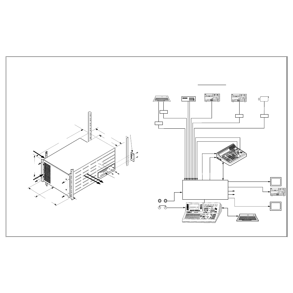
Typical System
24.8 in. (630 mm)
6
RACK-UNITS
10.5 in.
267 mm
19.00 in.
(483 mm)
17.25 in.
(438 mm)
TP0626-06
Standard 19" Rack
COOL AIR INTAKE
12.87 in.
(327 mm)
Attach to rack rail and insert
rear support plate.
REAR SUPPORT PLATE
EXHAUST AIR
COOL AIR INTAKE
Allow space on sides
for air flow
Allow space on
sides for air flow
Move as needed to fit into
rear bracket. Rear support
is required.
REAR SUPPORT BRACKET
REAR CLEARANCE 18" (457 mm)
WARNING
The frame is heavy. Use a mechanical
lifting device to lift it into position.
FRONT CLEARANCE
36" (914 mm)
Signal Processor Frame Installation
The Signal Processor Frame mounts in a standard 19-inch wide equipment rack and requires 6 rack units
of vertical space. Front and rear support are required. Leave some open space at the front of the frame for
module removal, at the back of the frame for cabling, and at the sides for cooling air flow.