Figure 2 – Grass Valley 4000 Remote Aux Panel User Manual
Page 9
Model 4000 Remote Aux Panel Upgrade Instruction Manual
3
Upgrade Instructions
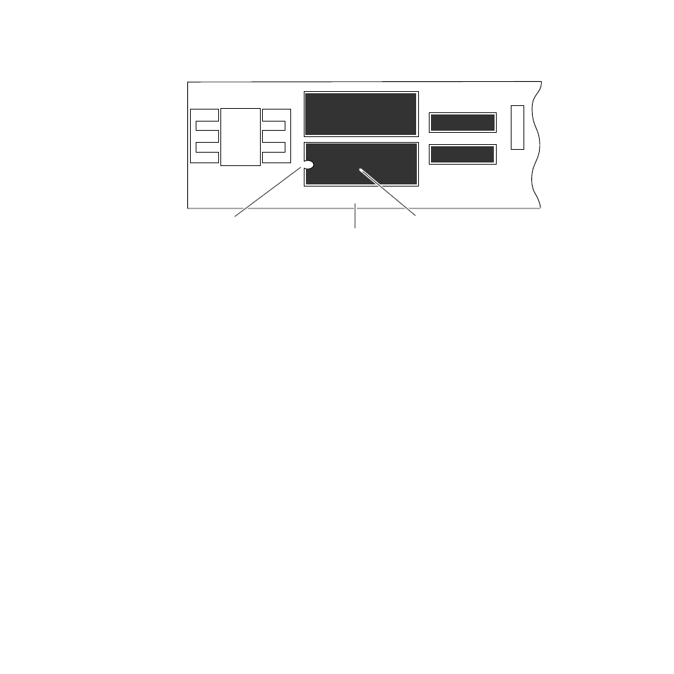
Figure 2. Model 4000 CPU Aux Control Board
6.
Using the extractor tool and proceeding with anti-static precautions,
carefully pry the Model 4000
CPU Aux Control EPROM from the
carrier by placing the tool under the EPROM and lifting it up and out
of the carrier.
7.
Orient the replacement CPU Aux Control EPROM by aligning its
notched edge with the notched edge on the carrier (
it firmly into the carrier.
8.
Replace the back plate and use a 3/16 inch nutdriver to replace the jack
screws on either side of the Joystick Override connector.
9.
Using a #10 Torx screwdriver, replace the center screw on the back
plate.
10.
Using a 5/16 inch nutdriver, replace the nuts and screws holding the
back plate onto the panel.
11.
Reconnect the DC power, communications, and Joystick Override
cables to the rear of the Remote Aux panel.
12.
Place the label provided in the kit on the front of the Remote Aux panel
to designate it as a Kalypso Remote Aux panel. This completes the
upgrade.
8079_00_01_r0
Model 4000 CPU Aux Control Board
Model 4000 CPU Aux Control EPROM
Notched Area on EPROM and Carrier
U2
U1